ON THE USE OF CONTROL ... Gabriel E. Ajayi*
advertisement
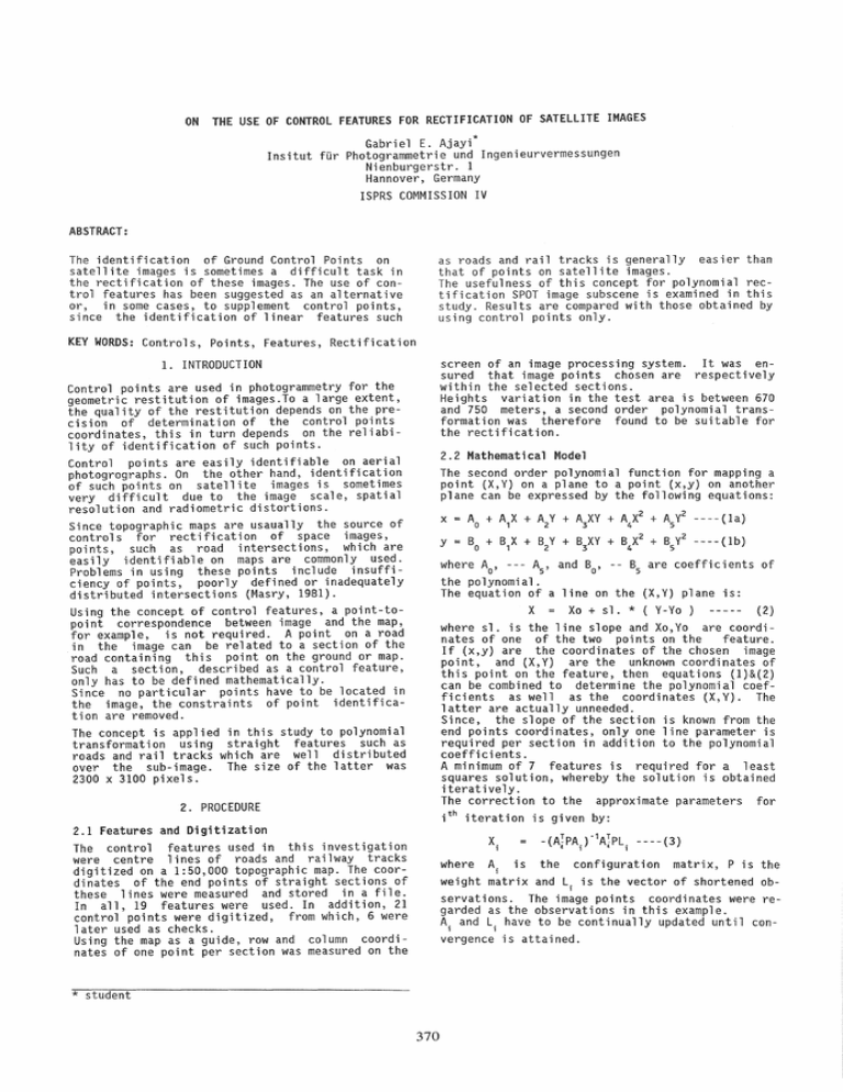
ON THE USE OF CONTROL FEATURES FOR RECTIFICATION OF SATELLITE IMAGES Gabriel E. Ajayi* Insitut fUr Photogrammetrie und Ingenieurvermessungen Ni enburgerstr. 1 Hannover, Germany ISPRS COMMISSION IV ABSTRACT: The identification of Ground Control Points on satellite images is sometimes a difficult task in the rectification of these images. The use of control features has been suggested as an alternative or, in some cases, to supplement control points, since the identification of linear features such as roads and rail tracks is generally easier than that of points on satellite images. The usefulness of this concept for polynomial rectification SPOT image subscene is examined in this study. Results are compared with those obtained by using control points only. KEY WORDS: Controls, Points, Features, Rectification screen of an image processing system. It was ensured that image points chosen are respectively within the selected sections. Heights variation in the test area is between 670 and 750 meters, a second order polynomial transformation was therefore found to be suitable for the rectification. 1. INTRODUCTION Control points are used in photogrammetry for the geometric restitution of images.To a large extent, the quality of the restitution depends on the precision of determination of the control points coordinates, this in turn depends on the reliability of identification of such points. Control points are easily identifiable on aerial photogrographs. On the other hand, identification of such points on satellite images is sometimes very difficult due to the image scale, spatial resolution and radiometric distortions. Since topographic maps are usaually the source of controls for rectification of space images, points, such as road intersections, which are easily identifiable on maps are commonly used. Problems in using these points include insufficiency of points, poorly defined or inadequately distributed intersections (Masry, 1981). Using the concept of control features, a point-topoint correspondence between image and the map, for example, ;s not required. A point on a road in the image can be related to a section of the road containing this point on the ground or map. Such a section, described as a control feature, only has to be defined mathematically. Since no particular points have to be located in the image, the constraints of point identification are removed. The concept is applied in this study to polynomial transformation using straight features such as roads and rail tracks which are well distributed over the sub-image. The size of the latter was 2300 x 3100 pixels. 2.2 Mathematical Model The second order polynomial function for mapping a point (X,Y) on a plane to a point (x,y) on another plane can be expressed by the following equations: x y = Ao + A1X + A2Y + A3XY + A4X2 + Asy2 ----(la) Bo + B1X + B2 Y + B3 XY + B4X2 + BSy2 - - - - (1 b) where Ao' --- As' and Bo' -- Bs are coefficients of the polynomial. The equation of a line on the (X,Y) plane is: X = Xo + sl. * ( V-yo ) (2) where sl. is the line slope and XO,Yo are coordinates of one of the two points on the feature. If (x,y) are the coordinates of the chosen image point, and (X,Y) are the unknown coordinates of this point on the feature, then equations (1)&(2) can be combined to determine the polynomial coefficients as well as the coordinates (X,Y). The latter are actually unneeded. Since, the slope of the section ;s known from the end points coordinates, only one line parameter is required per section in addition to the polynomial coefficients. A minimum of 7 features is required for a least squares solution, whereby the solution is obtained iteratively. The correction to the approximate parameters for ith iteration is given by: 2. PROCEDURE 2.1 Features and Digitization The control features used in this investigation were centre lines of roads and railway tracks digitized on a 1:50,000 topographic map. The coordinates of the end points of straight sections of these lines were measured and stored in a file. In all, 19 features were used. In addition, 21 control points were digitized, from which, 6 were later used as checks. Using the map as a guide, row and column coordinates of one point per section was measured on the X.1 -(A TPA.)"1A iPL.1 ----(3) 1 " where Ai is the configuration matrix, P is the weight matrix and L.1 is the vector of shortened observations. The image points coordinates were regarded as the observations in this example. Ai and Li have to be continually updated until convergence is attained. * student 370 3. RESULTS In addition to the transformation using control features, a second order polynomial transformation with control points was also done for comparison. Fifteen (15) points were used in the point-topoint transformation, while 19 features were used in point-to-feature transformation. In each case, 6 independent check points were used. The following results were obtained: Mean errors on transformation points: (row and column directions respectively) Control Points: 1.0 & 0.9 pixels Control Features: 0.7 & 0.6 pixels Mean errors on check points: Control Points: 0.8 & 1.6 pixels Control Features: 1.0 & 1.2 pixels 4. DISCUSSION AND CONCLUSION The use of straight line features as controls requires that the image point falls on the straight line defined on the map or ground after transformation. This in turn requires that: · that the road or track actually be straight between the two points, otherwise, a more complex function would be required to define the feature. · that the two points must be chosen on the same part of the road or track, e.g centre line or edge, from which the image point has been chosen. For this reason, roads and tracks symbolized with very thin lines are most appropriate on maps. • most importantly, that the image point falls within the limits of the feature as defined by the two points on the map or ground. Approximate values of parameters are required for the iterative solution discussed above, these may be obtained by initially assuming a one-to-one correspondence between the image point and the midpoint of the two points chosen on the feature. The rate of convergence depends a lot on how good the initial approximations are. The results show that this concept can be used in place of the control points method. One of its disadvantages however is that for the same number of transformation parameters, the number of features required is higher than the number of points. This, in addition to the requirement for iterative solution, implies an increased computation. 5. REFERENCES Masry, S.E., 1981. Digital Mapping Using Entities: A New Concept. Photo Eng. and Remote Sensing, 47: 1561-1565 371


