Odd- and Even-Order Dispersion Cancellation in Quantum Interferometry Olga Minaeva, Cristian Bonato,
advertisement

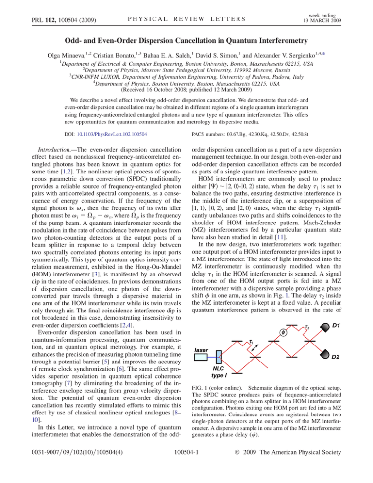
PRL 102, 100504 (2009) PHYSICAL REVIEW LETTERS week ending 13 MARCH 2009 Odd- and Even-Order Dispersion Cancellation in Quantum Interferometry Olga Minaeva,1,2 Cristian Bonato,1,3 Bahaa E. A. Saleh,1 David S. Simon,1 and Alexander V. Sergienko1,4,* 1 Department of Electrical & Computer Engineering, Boston University, Boston, Massachusetts 02215, USA 2 Department of Physics, Moscow State Pedagogical University, 119992 Moscow, Russia 3 CNR-INFM LUXOR, Department of Information Engineering, University of Padova, Padova, Italy 4 Department of Physics, Boston University, Boston, Massachusetts 02215, USA (Received 16 October 2008; published 12 March 2009) We describe a novel effect involving odd-order dispersion cancellation. We demonstrate that odd- and even-order dispersion cancellation may be obtained in different regions of a single quantum interferogram using frequency-anticorrelated entangled photons and a new type of quantum interferometer. This offers new opportunities for quantum communication and metrology in dispersive media. DOI: 10.1103/PhysRevLett.102.100504 PACS numbers: 03.67.Bg, 42.30.Kq, 42.50.Dv, 42.50.St Introduction.—The even-order dispersion cancellation effect based on nonclassical frequency-anticorrelated entangled photons has been known in quantum optics for some time [1,2]. The nonlinear optical process of spontaneous parametric down conversion (SPDC) traditionally provides a reliable source of frequency-entangled photon pairs with anticorrelated spectral components, as a consequence of energy conservation. If the frequency of the signal photon is !s , then the frequency of its twin idler photon must be !i ¼ p !s , where p is the frequency of the pump beam. A quantum interferometer records the modulation in the rate of coincidence between pulses from two photon-counting detectors at the output ports of a beam splitter in response to a temporal delay between two spectrally correlated photons entering its input ports symmetrically. This type of quantum optics intensity correlation measurement, exhibited in the Hong-Ou-Mandel (HOM) interferometer [3], is manifested by an observed dip in the rate of coincidences. In previous demonstrations of dispersion cancellation, one photon of the downconverted pair travels through a dispersive material in one arm of the HOM interferometer while its twin travels only through air. The final coincidence interference dip is not broadened in this case, demonstrating insensitivity to even-order dispersion coefficients [2,4]. Even-order dispersion cancellation has been used in quantum-information processing, quantum communication, and in quantum optical metrology. For example, it enhances the precision of measuring photon tunneling time through a potential barrier [5] and improves the accuracy of remote clock synchronization [6]. The same effect provides superior resolution in quantum optical coherence tomography [7] by eliminating the broadening of the interference envelope resulting from group velocity dispersion. The potential of quantum even-order dispersion cancellation has recently stimulated efforts to mimic this effect by use of classical nonlinear optical analogues [8– 10]. In this Letter, we introduce a novel type of quantum interferometer that enables the demonstration of the odd0031-9007=09=102(10)=100504(4) order dispersion cancellation as a part of a new dispersion management technique. In our design, both even-order and odd-order dispersion cancellation effects can be recorded as parts of a single quantum interference pattern. HOM interferometers are commonly used to produce either ji j2; 0i-j0; 2i state, when the delay 1 is set to balance the two paths, ensuring destructive interference in the middle of the interference dip, or a superposition of j1; 1i, j0; 2i, and j2; 0i states, when the delay 1 significantly unbalances two paths and shifts coincidences to the shoulder of HOM interference pattern. Mach-Zehnder (MZ) interferometers fed by a particular quantum state have also been studied in detail [11]. In the new design, two interferometers work together: one output port of a HOM interferometer provides input to a MZ interferometer. The state of light introduced into the MZ interferometer is continuously modified when the delay 1 in the HOM interferometer is scanned. A signal from one of the HOM output ports is fed into a MZ interferometer with a dispersive sample providing a phase shift in one arm, as shown in Fig. 1. The delay 2 inside the MZ interferometer is kept at a fixed value. A peculiar quantum interference pattern is observed in the rate of FIG. 1 (color online). Schematic diagram of the optical setup. The SPDC source produces pairs of frequency-anticorrelated photons combining on a beam splitter in a HOM interferometer configuration. Photons exiting one HOM port are fed into a MZ interferometer. Coincidence events are registered between two single-photon detectors at the output ports of the MZ interferometer. A dispersive sample in one arm of the MZ interferometer generates a phase delay (). 100504-1 Ó 2009 The American Physical Society PRL 102, 100504 (2009) PHYSICAL REVIEW LETTERS coincidences between two photon-counting detectors, D1 and D2, at the output ports of the MZ interferometer as a function of 1 . The interference profile has two distinct patterns. The central interference pattern depends only on even-order dispersion coefficients, while the peripheral pattern depends only on odd-order terms. This ability to manipulate and evaluate odd-order and even-order dispersion terms independently in a single quantum interferometer opens new perspectives in quantum communication and in precise optical measurement. Theoretical model.—For detectors D1 and D2 , much slower than the temporal coherence of the down-converted photons, the coincidence rate in such intensity correlation measurements is [12] Z Z Rc ð1 ; 2 Þ ¼ dt1 dt2 Gð2Þ ðt1 ; t2 Þ; (1) Gð2Þ ðt with 1 ; t2 Þ the second-order correlation function ð2Þ G ðt1 ; t2 Þ: 2 ^ ðþÞ Gð2Þ ðt1 ; t2 Þ ¼ jh0jE^ ðþÞ 1 ðt1 ÞE2 ðt2 Þjij : where fð!Þ is a photon wave packet spectral function defined by the phase-matching condition in the nonlinear material, 0 ¼ p =2 is a central frequency of each wave packet, !s ¼ 0 þ ! is the signal photon frequency, and !i ¼ 0 ! is the idler frequency. The phase shift ð!Þ acquired by the broadband optical wave packet as it travels through a dispersive material could be expanded in a Taylor’s series [13]: ð!s;i Þ ¼ c0 þ c1 ð!s;i 0 Þ þ c2 ð!s;i 0 Þ2 þ c3 ð!s;i 0 Þ3 þ ; In the optical setup of Fig. 1, the dispersive material providing phase shift ð!Þ could be situated in three possible locations. When the sample is placed on an arm of the HOM interferometer, it leads to the well-known even-order dispersion cancellation effect [4]. It may be shown that the presence of a dispersive material between the two interferometers does not affect the coincidence interferogram. We thus concentrate on the most interesting case: we place the dispersive sample of phase shift ð!Þ inside the MZ interferometer, with delay 2 set to a fixed value, and 1 as the variable parameter. Following the usual formalism [12], one can show that the coincidence rate between the detectors is Z Rc ð1 ; 2 Þ ¼ d!½0 ð!; 2 Þ ð!; 2 Þ ½fð!Þf ð!Þ þ fð!Þf ð!Þe2i!1 ; (6) where 0 is a constant, ð!; 2 Þ ¼ e2i!2 eið0 !Þ eið0 þ!Þ þ c:c:; (2) ðþÞ EðþÞ 1 ðt1 Þ and E2 ðt2 Þ are the electrical field operators at the surfaces of detectors D1 and D2 , respectively. 1 Z p ffiffiffiffiffiffi ffi d!j ei!j tj b^j ð!j Þ; ðt Þ ¼ (3) E^ ðþÞ j j 2 where b^j ð!j Þ is the mode operator at detector j, expressed in terms of the input field operators a^ j ð!j Þ [12]. The quantum state of light emitted in a frequency-degenerate noncollinear type-I phase-matching SPDC process with a monochromatic pump p is Z ji / d!fð!Þa^ y1 ð0 þ !Þa^ y2 ð0 !Þj0i; (4) (5) where the linear term c1 represents the group delay and the second-order term c2 is responsible for group delay dispersion. In a conventional white-light interferometer, c1 is responsible for a temporal shift of the interference pattern envelope, c2 causes its temporal broadening, while c3 provides a nonsymmetric deformation of the wave packet envelope. Higher-order terms might be included when a strongly-dispersive material is used or in the case of extremely broadband optical wave packets. week ending 13 MARCH 2009 (7) and ð!; 2 Þ ¼ e2i0 2 eið0 !Þ eið0 þ!Þ þ c:c: (8) Although not obvious from the form of Eq. (6), Rc ð1 ; 2 Þ is a real function for any spectrum fð!Þ, as can be seen by rewriting Eq. (6) in manifestly real form: Z Rc ð1 ; 2 Þ ¼ d!fjfð!Þj2 þ jfð!Þj2 þ ½e2i!1 fð!Þf ð!Þ þ c:c:g ½0 ð!Þ ð!Þ: (9) This fact ensures that the technique demonstrated here applies to all types of broadband frequency-anticorrelated states of light, including those with nonsymmetric spectral profiles produced in chirped periodically-polled nonlinear crystals. The final coincidence counting rate Rc ð1 ; 2 Þ of Eq. (6) may also be written as a linear superposition: Rc ð1 ; 2 Þ ¼ B þ R0 ð1 Þ Reven ð1 ; 2 Þ Rodd ð1 ; 2 Þ: (10) The first coefficient B incorporates all terms that are not dependent on the variable delay 1 , providing a constant after integration. It establishes a baseline level for the quantum interferogram. The following terms, Z R0 ð1 Þ ¼ 4 d!fð!Þf ð!Þe2i!1 ; (11) Reven ð1 ; 2 Þ ¼ 100504-2 Z d!fð!Þf ð!Þ e2i!1 ½e2i0 2 eið0 !Þ eið0 þ!Þ þ e2i0 2 eið0 !Þ eið0 þ!Þ ; (12) PRL 102, 100504 (2009) Rodd ð1 ; 2 Þ ¼ Z PHYSICAL REVIEW LETTERS week ending 13 MARCH 2009 d!fð!Þf ð!Þ ½e2i!ð1 þ2 Þ eið0 !Þ eið0 þ!Þ þ e2i!ð1 2 Þ eið0 !Þ eið0 þ!Þ (13) are responsible for the shape of the interference pattern. The term R0 ð1 Þ represents a peak centered at 1 ¼ 0 that is simply a Fourier transform of the down-converted radiation spectrum and is insensitive to the dispersion associated with ð!Þ. Since Reven ð1 ; 2 Þ is dependent on the sum ð0 !Þ þ ð0 þ !Þ, it is sensitive only to even-order terms in the expansion Eq. (5). This manifests odd-order dispersion cancellation and generates a dispersion-broadened function centered around 1 ¼ 0. The last term Rodd ð1 ; 2 Þ, in contrast, is sensitive only to odd-order dispersion terms in ð!Þ. This term demonstrates the well-known even-order cancellation. The coefficients e2i!ð1 þ2 Þ and e2i!ð1 2 Þ shift the two dips away from the center of the interference pattern in opposite directions. Such decomposition of quantum interference terms makes it possible to observe odd-order and evenorder dispersion cancellation effects in two distinct regions of the coincidence interferogram. Example.—Our results are illustrated by a numerical example of quantum interference for a 3-mm thick slab of a strongly-dispersive optical material ZnSe, inserted in one arm of the MZ interferometer to provide the phase shift ð!Þ. In this experiment, we assume the use of frequencyentangled down-converted photons with a 100-nm wide spectrum. As illustrated in Fig. 2, one can identify the narrow peak R0 ð1 Þ in the center, which is insensitive to dispersion, along with the component Reven ð1 ; 2 Þ, which is broadened by even-order dispersion contributions only. This central component of the interferogram illustrates the odd-order dispersion cancellation effect. Two symmetric side dips Rodd ð1 ; 2 Þ appear shifted far away from the central peak by the group velocity delay c1 acquired by entangled photons inside the dispersive material. However, this shift can be controlled by properly adjusting the value of the fixed delay 2 . Such a simple adjustment moves both dips back closer to the center and makes it convenient for observing both dispersion cancellation features in a single scan of the variable delay line (1 ) inside the HOM interferometer (see Fig. 2). The appearance of asymmetric fringes on the side of two dips is a clear sign of the third-order dispersion [13]. Discussion.—This result can also be understood physically by analyzing all possible probability amplitudes that lead to measured coincidence events between D1 and D2. The MZ interferometer input is a pair of spectrallyentangled photons separated by time delay 1 ; if the leading photon has a high frequency, the lagging photon will have a low frequency, and vice versa. We consider first the case when no dispersive element is present, so that the MZ interferometer introduces only a time delay 2 between its FIG. 2 (color online). The normalized coincidence rate as a function of 1 when a 3-mm thick ZnSe sample is placed in the MZ interferometer. The fixed delay 2 ¼ 26 ps is used. The insert illustrates the odd-order dispersion contribution. two arms. We assume that 2 is much greater than the photon wave packet width, c . To explain the dependence of the photon coincidence rate on 1 , as shown in Fig. 2, we consider three processes occurring at the input ports of the last beam splitter in the MZ interferometer: (1) If j1 j > c and j2 1 j > c , then the two photons arriving at the final beam splitter will be distinguishable, so that no quantum interference is exhibited. (2) If j1 j j2 j, so that j2 1 j < c , then quantum interference can occur when the leading photon takes the long path of the MZ interferometer and the lagging photon takes the short path. The two arrive almost simultaneously (within a time c ) at the two ports of the final beam splitter. Then the HOM effect is exhibited at the beam splitter, albeit with only 25% visibility because of the presence of the other possibility that both photons arrive at a single port, leading to a background coincidence rate independent of 1 . From a different perspective, one may regard this scenario as similar to that obtained in a Franson interferometer [14], for which photon pairs follow long-long or short-short paths. This scenario explains the components of the coincidence interferogram near 1 ¼ 2 , and in this case the two spectrally-entangled photons entering separate ports of the final beam splitter lead to quantum interference accompanied by even-order dispersion cancellation. (3) Finally, when j1 j < c , then one possibility is that the photons arrive at separate input ports of the final beam splitter. Since these photons are separated by a time 2 c , they are distinguishable and do not contribute to quantum interference. The other possibility is that the pair arrive at the same beam splitter input port. In this case, upon transmission or reflection at the beam splitter there are two alternatives for producing coincidence: transmission of the high-frequency photon and reflection of the lowfrequency photon, or vice versa. This explains the compo- 100504-3 PRL 102, 100504 (2009) PHYSICAL REVIEW LETTERS nent of the coincidence interferogram near 1 0. In this scenario, which involves two spectrally-entangled photons entering a single port of a beam splitter, quantum interference is accompanied by odd-order dispersion cancellation. We thus see that the quantum interference effects exhibited in scenarios (2) and (3) are accompanied by dispersion cancellation—although in opposite manners in the two cases. In conclusion, we have demonstrated a new effect in which even- and odd-order dispersion cancellations appear in different regions of a single interferogram. This is achieved via frequency-anticorrelated photons in a new quantum interferometer formed by a variable delay HOM interferometer followed by a single-input, fixed-delay Mach-Zehnder interferometer. The possibility of independently evaluating even- and odd-order dispersion coefficients of a medium has potential for applications in quantum communication and in quantum metrology of complex dispersive photonics structures. In particular, the ability to accurately characterize higher-order dispersion coefficients is of great interest in the study of flatteneddispersion optical fibers [15,16] and in dispersion engineering with metamaterials [17]. The demonstrated potential of even-order dispersion cancellation has stimulated the search for classical analogues [8,9]. We expect that the scheme presented here would also trigger the similar development of nonlinear optical techniques mimicking this quantum effect. Finally, note that our apparatus may be extended by adding a second Mach-Zehnder to the unused HOM output port, allowing the investigation of new fourphoton interference effects. We would like to thank Andrey Antipov from SUNY Buffalo for assistance with numerical simulations. This work was supported by a U. S. Army Research Office (ARO) Multidisciplinary University Research Initiative (MURI) grant; by the Bernard M. Gordon Center for Subsurface Sensing and Imaging Systems (CenSSIS), an week ending 13 MARCH 2009 NSF Engineering Research Center; by the Intelligence Advanced Research Projects Activity (IARPA) and ARO through Grant No. W911NF-07-1-0629. *Corresponding author. alexserg@bu.edu [1] J. D. Franson, Phys. Rev. A 45, 3126 (1992). [2] A. M. Steinberg, P. G. Kwiat, and R. Y. Chiao, Phys. Rev. A 45, 6659 (1992). [3] C. K. Hong, Z. Y. Ou, and L. Mandel, Phys. Rev. Lett. 59, 2044 (1987). [4] A. F. Abouraddy et al., Phys. Rev. A 65, 053817 (2002). [5] A. M. Steinberg, P. G. Kwiat, and R. Y. Chiao, Phys. Rev. Lett. 68, 2421 (1992). [6] V. Giovannetti, S. Lloyd, and L. Maccone, Nature (London) 412, 417 (2001). [7] M. B. Nasr, B. E. A. Saleh, A. V. Sergienko, and M. C. Teich, Phys. Rev. Lett. 91, 083601 (2003). [8] B. I. Erkmen and J. H. Shapiro, Phys. Rev. A 74, 041601 (R) (2006). [9] K. J. Resch et al., Opt. Express 15, 8797 (2007). [10] R. Kaltenbaek, J. Lavoie, D. Biggenstaff, and K. J. Resch, Nature Phys. 4, 864 (2008). [11] R. A. Campos, B. E. A. Saleh, and M. C. Teich, Phys. Rev. A 42, 4127 (1990). [12] M. H. Rubin, D. N. Klyshko, Y. H. Shih, and A. V. Sergienko, Phys. Rev. A 50, 5122 (1994). [13] J.-C. Diels and W. Rudolph, Ultrashort Laser Pulse Phenomena (Elsevier Inc. Academic Press, London, 2006). [14] J. D. Franson, Phys. Rev. Lett. 62, 2205 (1989). [15] A. Ferrando, E. Silvestre, P. Andrées, J. Miret, and M. Andrés, Opt. Express 9, 687 (2001). [16] W. Reeves, J. Knight, P. S. Russell, and P. Roberts, Opt. Express 10, 609 (2002). [17] G. V. Eleftheriades and K. G. Balmain, NegativeRefraction Metamaterials (Wiley-IEEE Press, New York, 2005). 100504-4


