AN-1229 APPLICATION NOTE
advertisement
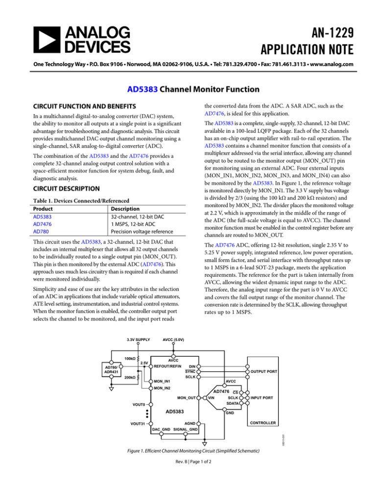
AN-1229 APPLICATION NOTE One Technology Way • P.O. Box 9106 • Norwood, MA 02062-9106, U.S.A. • Tel: 781.329.4700 • Fax: 781.461.3113 • www.analog.com AD5383 Channel Monitor Function CIRCUIT FUNCTION AND BENEFITS the converted data from the ADC. A SAR ADC, such as the AD7476, is ideal for this application. In a multichannel digital-to-analog converter (DAC) system, the ability to monitor all outputs at a single point is a significant advantage for troubleshooting and diagnostic analysis. This circuit provides multichannel DAC output channel monitoring using a single-channel, SAR analog-to-digital converter (ADC). The AD5383 is a complete, single-supply, 32-channel, 12-bit DAC available in a 100-lead LQFP package. Each of the 32 channels has an on-chip output amplifier with rail-to-rail operation. The AD5383 contains a channel monitor function that consists of a multiplexer addressed via the serial interface, allowing any channel output to be routed to the monitor output (MON_OUT) pin for monitoring using an external ADC. Four external inputs (MON_IN1, MON_IN2, MON_IN3, and MON_IN4) can also be monitored by the AD5383. In Figure 1, the reference voltage is monitored directly by MON_IN1. The 3.3 V supply bus voltage is divided by 2/3 (using the 100 kΩ and 200 kΩ resistors) and monitored by MON_IN2. The divider places the monitored voltage at 2.2 V, which is approximately in the middle of the range of the ADC (the full-scale voltage is equal to AVCC). The channel monitor function must be enabled in the control register before any channels are routed to MON_OUT. The combination of the AD5383 and the AD7476 provides a complete 32-channel analog output control solution with a space-efficient monitor function for system debug, fault, and diagnostic analysis. CIRCUIT DESCRIPTION Table 1. Devices Connected/Referenced Product AD5383 AD7476 AD780 Description 32-channel, 12-bit DAC 1 MSPS, 12-bit ADC Precision voltage reference This circuit uses the AD5383, a 32-channel, 12-bit DAC that includes an internal multiplexer that allows all 32 output channels to be individually routed to a single output pin (MON_OUT). This pin is then monitored by the external ADC (AD7476). This approach uses much less circuitry than is required if each channel were monitored individually. The AD7476 ADC, offering 12-bit resolution, single 2.35 V to 5.25 V power supply, integrated reference, low power operation, small form factor, and serial interface with throughput rates up to 1 MSPS in a 6-lead SOT-23 package, meets the application requirements. The reference for the part is taken internally from AVCC, allowing the widest dynamic input range to the ADC. Therefore, the analog input range for the part is 0 V to AVCC and covers the full output range of the monitor channel. The conversion rate is determined by the SCLK, allowing throughput rates up to 1 MSPS. Simplicity and ease of use are the key attributes in the selection of an ADC in applications that include variable optical attenuators, ATE level setting, instrumentation, and industrial control systems. When the monitor function is enabled, the controller output port selects the channel to be monitored, and the input port reads 3.3V SUPPLY 100kΩ 2.5V AVCC (5.0V) AVCC REFOUT/REFIN AD780/ ADR431 200kΩ DIN SYNC SCLK OUTPUT PORT MON_IN1 AVCC MON_IN2 AD7476 CS MON_OUT VIN AD5383 VOUT31 SCLK INPUT PORT SDATA VOUT0 GND AGND CONTROLLER 08311-001 DAC_GND SIGNAL_GND Figure 1. Efficient Channel Monitoring Circuit (Simplified Schematic) Rev. B | Page 1 of 2 AN-1229 Application Note The AD5383 and the AD7476 must have ample supply bypassing of 10 µF in parallel with 0.1 µF on each supply pin, located as close to the packages as possible, ideally right up against the devices (this is not shown on the simplified diagram). The 10 µF capacitors are the tantalum bead type. The 0.1 µF capacitor must have low effective series resistance (ESR) and low effective series inductance (ESL), such as the common ceramic types that provide a low impedance path to ground at high frequencies to handle transient currents due to internal logic switching. LEARN MORE The power supply traces must be as wide as possible to provide low impedance paths and reduce the effects of glitches on the power supply line. Fast switching signals, such as clocks, must be shielded with ground runs to avoid radiating noise to other parts of the board and must never be run near the analog signals. A ground line routed between the SDATA and the SCLK lines helps reduce crosstalk between them (this is not required on a multilayer board, which has a separate ground plane; however, it is helpful to separate the lines). Avoid crossover of digital and analog signals. Run traces on opposite sides of the board at right angles to each other to reduce the effects of feedthrough on the board. A microstrip technique is recommended; however, it is not always possible with a double-sided board. In this technique, the component side of the board is dedicated to the ground plane and signal traces are placed on the solder side. Best layout and performance are achieved with at least a 4-layer multilayer board where there is a ground plane layer, a power supply layer, and two signal layers. MT-101 Tutorial, Decoupling Techniques. Analog Devices. COMMON VARIATIONS ADIsimPower Design Tool. Kester, Walt. 2005. The Data Conversion Handbook. Chapters 3 and 7. Analog Devices. MT-015 Tutorial, Basic DAC Architectures II: Binary DACs. Analog Devices. MT-031 Tutorial, Grounding Data Converters and Solving the Mystery of AGND and DGND. Analog Devices. Data Sheets and Evaluation Boards AD5383 Data Sheet. AD5383 Evaluation Board. AD7476 Data Sheet. AD780 Data Sheet. ADR431 Data Sheet. REVISION HISTORY 5/13—Rev. A to Rev. B Document Title Changed from CN-0015 to AN-1229 ....... Universal 8/09—Rev. 0 to Rev. A Updated Format .................................................................. Universal 11/08—Revision 0: Initial Version Pin-compatible versions of the AD7476 (10-bit AD7477 and 8-bit AD7478) are available for use in applications where lower resolution conversion is acceptable. This may be acceptable in many applications because the monitor function is an auxiliary function and is not part of the primary signal chain. Accuracy is not paramount, and the influence of using AVCC as a reference voltage is permissible. ©2008–2013 Analog Devices, Inc. All rights reserved. Trademarks and registered trademarks are the property of their respective owners. AN08311-0-5/13(B) Rev. B | Page 2 of 2
