Andrews Highlights Reference concepts derived from stakeholder objectives,
advertisement
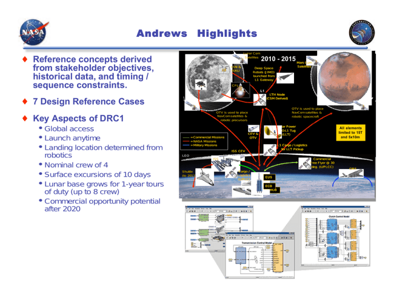
Andrews Highlights Lunar Com Lunar Com Satellites Satellites Reference concepts derived from stakeholder objectives, historical data, and timing / sequence constraints. 7 Design Reference Cases LSN & LSN & ISRU ISRU • • • • Global access Launch anytime Landing location determined from robotics Nominal crew of 4 Surface excursions of 10 days Lunar base grows for 1-year tours of duty (up to 8 crew) Commercial opportunity potential after 2020 Deep Space Deep(JIMO) Space Robots Robots (JIMO) launched from launched from L1 Gateway L1 Gateway CPL CPL LEO LEO Shuttle (toShuttle 2013) (to 2013) Solar Power Solar Power LEO-L1 Tug LEO-L1 (LLT) Tug (LLT) CEV & CEV & OTV OTV All elements All elements limited to 15T limited to 15T and 5x10m and 5x10m L1 Cargo / Logistics L1 / Logistics forCargo LLT Pickup for LLT Pickup ISS CEV ISS CEV ISS ISS Cargo / Cargo / Logistics Logistics (U/PLC) (U/PLC) LMO LMO OTV is used to place OTV is satellites used to place NavCom & NavCom satellites & robotic spacecraft robotic spacecraft OTV is used to place OTV is satellites used to place NavCom & NavCom satellites & robotic precursors robotic precursors = Commercial Missions Commercial == NASA MissionsMissions = NASAMissions Missions = Military = Military Missions Satellites Satellites L1 L1 LTH Node LTH Node (CSM Derived) (CSM Derived) LLO LLO Key Aspects of DRC1 • • • 2010 Com 2010- -2015 2015Mars Mars Com Commercial FreeCommercial Flyer @ 30 Free(U/PLCC) Flyer @ 30 deg. deg. (U/PLCC) EUS EUS ECB ECB RCB RCB ORS ORS Boeing Highlights Architecture driven from the Vision, lunar exploration objectives, lunar resource utilization, and national security Baseline architecture provides extensible capability for future exploration & supports future ventures L2 Equatorial EquatorialSite Site Spiral 2 & 3 South SouthPole PoleSite Site Architecture Summary • • • • • • • Earth-Moon L1 Rendezvous LEO aggregation of elements Reusable lunar module Single stage LM Anytime returns; L1 gateway Trip time extended by L1 operations 14 days - continuous/long duration lunar stays Spiral 1 L1 Launch Launch Vehicle Vehicle Options Options Spiral 4 & 5 Mars Site Assumption & Ground rules - Lunar polar water ice may be accessible - Necessary technologies at TRL 6 by PDR - Two launch providers - ETO capability limited to 20/45+ MT LV For crew return from Mars 250 225.5 225.5 225.5 4.5 6.7 4.5 6.7 4.5 6.7 10.9 10.9 10.9 200 208.7 Note: Does not include polar orbit with anytime abort 4.5 6.7 182.1 10.9 38.4 38.4 38.4 9.6 9.6 9.6 164.4 150 Mass (MT) Numerous architecture / design trades 4.5 6.7 35.6 10.1 8.6 155.8 4.1 6.7 4.5 6.7 13.3 21.9 11.5 6.5 28.3 64.9 64.9 15.3 64.9 60.2 7.6 SM Gross 5.6 53.6 100 44.3 12.8 12.8 46.6 12.8 11.0 11.0 50 9.7 9.3 64.9 64.9 64.9 60.2 46.6 44.3 0 9.3 Goal Baseline 12.8 Trade Baseline 12.8 SDLV 12.8 Common LV's 11.0 Dry Launch 9.7 LLO Rendezvous MM CM 53.6 11.0 Partial LLO Rendezvous Trade Results show masses needed in LEO for various cases LM Prop LM Dry ETS Prop ETS Dry ETS Prop ETS Dry Lockheed Martin Highlights Guiding Principals • • • Simultaneously address all Vision Objectives Start with Mars and work backwards Answer fundamental questions to determine post2025 future of exploration on Moon, Mars, Beyond Numerous trades being conducted POD Lunar Architecture Features (2018 -2023) Surface Science (e.g., geoscience networks) – Pursuing water/life clues – Providing global access to H20 ice at poles/near poles – Soon to be performing combined science, ISRU, engineering testbed missions – Improving rover duration and speed • Human missions likely to use fixed, near-equatorial site for surface stays of 30-630 days – – – – – – – Near the most desirable sites Low altitude to minimize entry/descent/landing difficulty Enables incremental build-up Most energy/mass efficient location More favorable thermal environment (20°C to -140°C) Safest approach Best solar fluence Sample returns (e.g, Moonrise @ Aitken Basin) Equatorial Outpost Astronomical observatory proof of concepts Communications via direct near-side broadband + global narrowband TC&C minisats TBD on-orbit CEV/LSAM lifeboats for anytime rescue Upgraded DSN Communications Low Lunar Orbit (LLO) CEV/LSAM staging Consolidated Mission Control LEO automated rendezvous and assembly Direct Earth re-entry and water recovery operations ETR launch operations • Cargo-only missions (Two 70mT) • Crew missions (Two 70mT or 70mT combined with single stick) Earth Solar Flare/ Warning System(s) Ground processing (crew, samples, systems) Sun 100 Normalized Cost for 5 Missions (% of maximum) Mars robotic precursors (orbiters and landers) already leading the way Roving robotic explorers Crew field work Exploration Approach • Moon Reconnaissance Orbiters (e.g, LRO) 80 60 • Fixed Outpost (pre-positioned and incrementally built- up) • Equatorial (+/-30°) focus for lunar testbed, ISRU, and science – Crewed remote landings elsewhere as warranted • Central location for surface safe haven and mission abort • Global access via human/robotic surface transportation (e.g., rovers, hoppers) Remote operations as warranted (e.g, robotic H2 O pilot at southern pole if ice is found) 314 Isp (Storables) in TEI and LSAM 363 Isp (LOX/CH4) in TEI and LSAM 454 Isp (LOX/LH2) in TEI and LSAM 1 40 20 0 2-Stage expendable LSAM LLO rendezvous (POD) 2-Stage 1-Stage expendable LSAM reusable LSAM L1 rendezvous LLO rendezvous 2 1-Stage reusable LSAM L1 rendezvous Northrop Grumman Highlights Guiding Principles • • • Simultaneously address each of the Vision Objectives Start with Mars and work backwards Answer the fundamental questions to determine the post-2025 future of exploration on Moon, Mars, and Beyond Numerous trades being conducted ETS -2s Transport CEV/ASDS in Parallel to L1 EML1 Parallel ETS -2 Earth De -Orbit ASDS Transports HM to Moon RM Return ETS -2/SM/RM Station Keep EML1 AS Transports HM to L1 ETS -2/SM/HM Earth De -Orbit ETS -2 Transports CEV to Direct Earth Insertion ETS -2s Transport CEV/ASDS Stacked to LLO LLO CEV/ASDS in LLO Stacked ASDS Transports HM to Moon ETS -2 Discarded RM Return SM/RM in LLO ETS -2 Earth De -Orbit Exploration Approach • Polar landing site 180 days surface duration Safe-haven abort; Implicit Rescue with Responsiveness 0-4 crew members Mars preparation has two components • • Technology demonstration and test Operational experience: “Lessons Learned” CEV Transports from LLO to Earth Insertion AS Discarded SM/HM Earth De -Orbit CEV/AS in LLO Anytime Return Capabilities APC=Ascent Plane Change CEV: Equatorial Base: 0 deg APC: 0 m/s TEI: 987 m/s IMLEO (kg) • • • AS Transports HM to LLO CEV: Polar Orbit Base: 70 deg APC: 560 m/s TEI: 1387 m/s APC on CEV SM APC on LM AS CEV: Polar Orbit Base: 56 deg APC: 942 m/s TEI: 1387 m/s APC on LM AS APC on CEV SM CEV: Polar Orbit Base: 43 deg APC: 1285 m/s TEI: 1387 m/s APC on LM AS CEV: L1 Base: Any APC: 0 m/s TEI: 677 m/s APC on CEV SM CTS-101-02 CTS-103 LLO -A HM RM SM AS DS ETS-A ETS-B LLO- B LLO- C LLO- D LLO -E LLO -F LLO- G L1 Orbital Sciences Highlights Vision Mapped to Objectives, Missions, Functions, and Requirements Numerous trades being conducted Example Habitation Alternatives • • • Multiple Outpost Capability Anywhere on Lunar Surface? Lunar Logistics Base: Establish Single Lunar Base and Provide for Distributed Exploration Capability? Lunar Orbiter: Provide 90 Day Capable Lunar Orbiter With Surface Excursion Capability Anywhere on Lunar Surface? Observations • • • • Coupling of Lunar Base Selection and Lunar Abort/Safe Haven Capability It’s Primarily a Transportation and Logistics Problem Lunar/Mars Operations Need to Be Compatible and Traceable Need a Budget Strategy at Spiral Transitions to Ensure Sustainability Raytheon Vision for Space Exploration drives exploration strategy • • Common infrastructure elements across missions Not dependent on changes to political viability of a single mission Numerous trades being conducted • • • Mission architecture related System sensitivities Technologies Applicability of Lunar Operations to Mars Exploration Identified Key Architectural Construct • • • • • • • Initial basing at South Pole Low-Lunar Orbit staging for cargo L1 staging for crew Lunar regolith used for crew protection from lunar environment Launch vehicle strategy being traded 3 crew members provide the operational and safety margins desirable at minimum cost Critical technologies identified Highlights SAIC Highlights Study Status • • • • Preliminary analysis of Initial Concept for Technical Solution (ICTS) 20-mission campaign is complete Conservative assumptions have been made throughout this preliminary analysis Results indicate that the baseline campaign is both feasible and achievable Additional trade studies are underway Campaign Studies Conducted • • • • Mass Flow Loss of Mission / Loss of Crew Risk Mitigation Measure Launch Manifest Trades Figures of Merit Assessments • • • • Safety & Mission Success: LOM & LOC risks have been identified and initial values generated Effectiveness: Being explored Extensibility: Campaign is based around developing long-duration mission capability without resupply (in preparation for Mars surface missions) and selected subsystems Affordability: Under development Draper / MIT Highlights Stakeholder Value Analysis Approach: • • • • • Stakeholders identified (14) Stakeholder needs defined (~90) Exploration objectives (24) Technical architecture proximate measures (~18) Indicator metrics (~40) Mars Back Emphasis QFD Tool utilized to screen options • For over 600 itineraries, and fixed technology/operational decisions, optimization determines best mix of technologies Numerous architecture, system, and technology trades being conducted. Key Findings to Date • • A sustainable exploration program must focus on delivering value throughout its lifetime to all stakeholders A Mars-back focus should be maintained throughout the architecture and mission development process Schafer Highlights Architecture Overview • • • • • • • Emphasizes Gateway Architecture Architecture Fosters In Situ Resource Utilization (ISRU) L1 Refueling and resupply Direct return from lunar surface Off Earth Robotic Assembly, Set-up, and Operation For All Infrastructure Robotic Reconnaissance Missions Select Near Lunar Equator And South Pole Locations For Probable Extended Presence And Continued Exploration Assume One Crewed Mission Per Year Over 5-year Campaign In Spiral-2 Drivers and Sensitivities • • • • • • CEV Mass Strongly Influences Propellant Required Radiation Shielding Of CEV Is Severe Penalty Launch Of Propellant Mass To LEO Dominates All Architectures CONUS Landing Stresses CEV For Direct Return LV Capabilities And Lift Mass To LEO CEV Crew Size Reliability Of Storage And Transfer Of Cryo Propellant In Space ISRU Propellant Or LunOX Production Effectiveness For Future Spiral-3 Missions Abort Scenarios For Crew Safety Determine Size And Mass Of L1 Infrastructure 80 70 60 Number of Launches • • • 50 40 30 20 10 0 L1 8mt CEV L1 12mt CEV LEO 12mt CEV Prop. L1 12mt CEV, 8mt Lander CEV Lander L1, 12mt CEV, 12mt Lander Cargo LEO, 16mtCEV Supplies L1, 16mt CEV, 8mt Lander L1, 16mt CEV 12mt Lander SpaceHab Highlights Architecture Overview • • • • • • Maximize system modularity to the greatest extent possible Each element will have the capability to operate alone or in conjunction with other elements All non-crewed elements are launched on commercial Expendable Launch Vehicles (ELVs) with a lift capability of at least 15 metric tons. The Crew Exploration Vehicle (CEV) is launched on a human rated launch system. The CEV is sized to accommodate four crewmembers. Reuse of systems Key Technologies Identified to Date • • • • • • Automated Rendezvous, Proximity Operations and Docking (ARPOD) Liquid Cryo Propellant Management Extended-duration power generation (Nuclear Power) Interplanetary communications relay Regenerative ECLSS Radiation Shielding t-Space Highlights An Engine for Free Enterprise • • • • Pay-for-results rather than pay-for-analysis Businesses can grow from earnings NASA-commercial partnerships will build a more resilient system With NASA as an enabling partner, firms can transform space into a net generator of tax revenues instead of an endless consumer of them An Open Frontier • • • • • • Government leadership rather than government ownership Flotilla expeditions, not single vehicles Smaller, simpler vehicles For the first 20-40 expeditions, it will be cheaper to use more propellant than to create new optimized vehicles (lunar lander) Simplicity equals reliability Enable commercial passenger markets S2CEV for crew S1CXV for crew CCB for S1 Triple CCB for S2 AirLaunch LLC Option SpaceX Kistler Mission Definition • • • Land at south pole quickly Each expedition builds in-space infrastructure Public must see understandable value S1Tanker for propellant Future LSAM Derivative S1 S2 Ground Launch Options Launch Elements FY 04 FY 08 FY 06 Spiral 1 Formulation Approval Spiral 1 Program Approval FY 14 PRE-PHASE A ACTIVITIES Spiral 1 Production Approval PHASE A: MISSION DEFINITION PHASE C: FINAL DESIGN B C PHASE D: FABRICATE/OPERATE D STUDY PDR DESIGN CDR Risk Reduction 2008 Demo CEV RFP SPIRAL I PROJECTS Spiral 1 Design Approval A SRR DESIGN CEV Un-Crewed Flight FABRICATE PDR DESIGN DESIGN STUDY Risk Reduction 2008 Demo Non Traditional Approach ETO RELATED PROJECTS FY 12 FY 10 PHASE B: PRELIMINARY DESIGN REQUIREMENTS DEFINITION AGENCY MILESTONES CEV Project Technology Infusion BAA BAA Safety Net BAA BAA S. Integrator RFP Potential Commercial Solution ESRT/HSRT EFFORTS ESRT/HSRT RESEARCH SYSTEM ENGINEERING AND INTEGRATION CEV Crewed Flight FY 04 FY 08 FY 06 Spiral 1 Formulation Approval Spiral 1 Program Approval FY 14 PRE-PHASE A ACTIVITIES Spiral 1 Production Approval PHASE A: MISSION DEFINITION PHASE C: FINAL DESIGN B C PHASE D: FABRICATE/OPERATE D STUDY PDR DESIGN CDR Risk Reduction 2008 Demo CEV RFP SPIRAL I PROJECTS Spiral 1 Design Approval A SRR RELATED PROJECTS FY 12 FY 10 PHASE B: PRELIMINARY DESIGN REQUIREMENTS DEFINITION AGENCY MILESTONES CEV Project DESIGN CEV Un-Crewed Flight FABRICATE PDR DESIGN DESIGN STUDY Risk Reduction 2008 Demo Technology Infusion BAA BAA Safety Net BAA BAA S. Integrator RFP ESRT/HSRT EFFORTS ESRT/HSRT RESEARCH SYSTEM ENGINEERING AND INTEGRATION CEV Crewed Flight FY 04 FY 08 FY 06 Spiral 1 Formulation Approval Spiral 1 Program Approval FY 14 PRE-PHASE A ACTIVITIES Spiral 1 Production Approval PHASE A: MISSION DEFINITION PHASE C: FINAL DESIGN B C PHASE D: FABRICATE/OPERATE D STUDY PDR DESIGN CDR Risk Reduction 2008 Demo CEV RFP SPIRAL I PROJECTS Spiral 1 Design Approval A SRR RELATED PROJECTS FY 12 FY 10 PHASE B: PRELIMINARY DESIGN REQUIREMENTS DEFINITION AGENCY MILESTONES CEV Project DESIGN CEV Un-Crewed Flight FABRICATE PDR DESIGN DESIGN STUDY Risk Reduction 2008 Demo Technology Infusion BAA BAA Safety Net BAA BAA S. Integrator RFP ESRT/HSRT EFFORTS ESRT/HSRT RESEARCH SYSTEM ENGINEERING AND INTEGRATION CEV Crewed Flight Exploration Systems Mission Directorate www.nasa.gov
