Uncontrolled When Printed Document comes into force 07/06/2014
advertisement
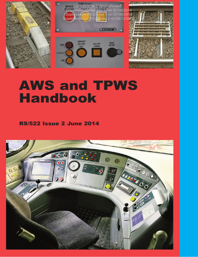
Uncontrolled When Printed Document comes into force 07/06/2014 Supersedes RS522 Iss 1 on 07/06/2014 Superseded by RS522 Iss 3 on 05/12/2015 AWS and TPWS Handbook RS/522 Issue 2 June 2014 Uncontrolled When Printed Document comes into force 07/06/2014 Supersedes RS522 Iss 1 on 07/06/2014 Superseded by RS522 Iss 3 on 05/12/2015 Published by: RSSB Block 2 Angel Square 1 Torrens Street London EC1V 1NY Contents approved by Traffic Operation and Management Standards Committee. For information regarding this document, contact: enquirydesk@rssb.co.uk AWS and TPWS Handbook RS/522 First issued June 2012 Issue 2, June 2014 © Copyright 2014 Rail Safety and Standards Board Uncontrolled When Printed Document comes into force 07/06/2014 Supersedes RS522 Iss 1 on 07/06/2014 Superseded by RS522 Iss 3 on 05/12/2015 You will need this AWS and TPWS handbook if you carry out the duties of a: • driver • signaller. i This symbol indicates extra information or guidance regarding the instructions. 1 Uncontrolled When Printed Document comes into force 07/06/2014 Contents Supersedes RS522 Iss 1 on 07/06/2014 Superseded by RS522 Iss 3 on 05/12/2015 1 2 3 2 Automatic warning system 1.1 General information 1.2 Track equipment 1.3 Train equipment 1.4 AWS indications and their meanings 1.5 Areas where AWS is not provided 1.6 AWS suppression and AWS cancelling indicators Train protection and warning system 2.1 General information 2.2 Track equipment 2.3 Train equipment 2.4 Signal box equipment Failures and irregularities 1 Uncontrolled When Printed Document comes into force 07/06/2014 Automatic warning system Supersedes RS522 Iss 1 on 07/06/2014 Superseded by RS522 Iss 3 on 05/12/2015 1.1 General information 1.1.1 Background The Automatic Warning System (AWS) has been implemented as the national warning system on the UK main line passenger railway network since the 1950s. 1.1.2 The purpose of AWS The original concept of AWS was to provide the driver with an audible and visual indication of whether the distant signal was clear or at caution. Should the driver fail to respond to a warning indication, an emergency brake application will be initiated. Since the introduction of multi-aspect signalling, the majority of signals are fitted with AWS. It should be noted that AWS does not relieve the driver of the responsibility of observing and obeying lineside signals and indicators. 1.1.3 Provision of AWS AWS consists of track and train equipment. The track equipment consists of an AWS magnet that is normally provided 180 metres (approximately 200 yards) on the approach to a signal. The AWS magnet may be positioned at a greater distance from the signal on high-speed lines or at a lesser distance from the signal on lower speed and platform lines. This system works by the train detecting sequences and polarities of magnetic fields passing between the track equipment and the train equipment via a receiver under the train. At through stations where the permitted speed is 30 mph or less and the layout is complex, AWS track equipment need not be provided. Where this occurs, these are called AWS gap areas. 3 1 Uncontrolled When Printed Document comes into force 07/06/2014 Automatic warning system Supersedes RS522 Iss 1 on 07/06/2014 Superseded by RS522 Iss 3 on 05/12/2015 AWS magnets are not provided at semaphore stop signals. Where a distant signal is mounted on the same post as a semaphore stop signal then AWS is provided for the distant signal. Where a line is not fitted with AWS, this is shown in the Sectional Appendix. Where a reduction in permissible speed is provided with a warning indicator (i.e. the permissible speed on the approach is 60 mph or more and the reduction in the permissible speed is at least one third) an AWS permanent magnet is provided 180 metres (approximately 200 yards) on the approach to the warning indicator. These are sometimes referred to as ‘Morpeth magnets’. AWS magnets are also used to alert the driver to the following. • Level crossing warning boards or indicators. • Temporary speed restriction warning boards. • Emergency speed restriction warning boards and emergency indicators. 1.2 Track equipment The AWS track equipment comprises various components mounted in the centre of the four-foot. Permanent magnet The train will first encounter a permanent magnet. Following the train passing over a permanent magnet where an electromagnet is either not provided or not energised, the AWS gives a warning indication to the driver. Electromagnet An energised electromagnet, when presented after the permanent magnet, gives the driver a ‘clear’ indication when approaching a green signal or a semaphore distant signal showing ‘clear’. 4 1 Uncontrolled When Printed Document comes into force 07/06/2014 Automatic warning system Supersedes RS522 Iss 1 on 07/06/2014 Superseded by RS522 Iss 3 on 05/12/2015 electromagnet permanent magnet Direction of travel An example of AWS track equipment Suppressor magnet Suppressor magnets are used to suppress permanent magnets when they are not required to apply to a train movement (for example, magnets applicable to the opposite direction on a single or bi-directional line). Depot test magnet A permanent magnet, used to test the operation of a train’s AWS equipment, may be provided at the exit of certain maintenance depots. Portable magnet Portable AWS magnets are provided to give a warning to the driver, on the approach to temporary and emergency speed restrictions. An example of a portable magnet 5 1 1.3 Uncontrolled When Printed Document comes into force 07/06/2014 Automatic warning system Supersedes RS522 Iss 1 on 07/06/2014 Superseded by RS522 Iss 3 on 05/12/2015 Train equipment The following equipment is provided on each fitted traction unit. AWS receiver The AWS receiver is located under a traction unit and detects the sequences and polarities of magnetic fields from the AWS track magnets. AWS audible indicator The audible indicator gives a warning or a clear indication that is distinguishable from all other audible cab indications. The audible indication is either: • a clear indication (bell or electronic equivalent), or • a warning indication (horn or electronic equivalent). AWS visual indicators The visual indications are as follows. The black indication advises the driver that the associated signal is showing a green aspect or ‘all clear’. It also advises the driver that the audible warning has not been acknowledged and, if not acknowledged, the brakes will be applied. The yellow and black indication advises the driver that a warning indication has been acknowledged. 6 1 Uncontrolled When Printed Document comes into force 07/06/2014 Automatic warning system Supersedes RS522 Iss 1 on 07/06/2014 Superseded by RS522 Iss 3 on 05/12/2015 AWS/TPWS acknowledgement button The AWS/TPWS acknowledgement button is used to acknowledge an AWS audible warning. If an AWS audible warning is not acknowledged within two to three seconds an emergency brake application will occur. 1.4 AWS indications and their meanings 1.4.1 Warning indication The driver will receive a warning indication in the driving cab on the approach to a: • colour light signal displaying a single or double yellow (steady or flashing) or a red aspect • semaphore distant signal displaying a caution indication • warning indicator provided for some permissible speed reductions • warning board provided for an automatic barrier crossing locally monitored (ABCL), an automatic open crossing locally monitored (AOCL) or an open crossing (OC) • warning board or emergency indicator for a temporary or emergency speed restriction • cancelling indicator for an AWS warning which does not apply to the train. The driver will also receive a warning indication when passing over an AWS depot test magnet. AWS is not capable of distinguishing between a red, double yellow or single yellow aspect. 7 1 1.4.2 Uncontrolled When Printed Document comes into force 07/06/2014 Automatic warning system Supersedes RS522 Iss 1 on 07/06/2014 Superseded by RS522 Iss 3 on 05/12/2015 Clear indication The driver will receive a clear indication in the driving cab when approaching: • a colour light signal showing a green aspect, or • a semaphore distant signal displaying a clear indication. The driver does not have to acknowledge a clear indication. 1.5 Areas where AWS is not provided In some AWS fitted areas AWS equipment is not provided throughout. These areas are identified with the following signs. Where AWS is not provided at a station on a line equipped with AWS. Start of AWS gap End of AWS gap Where AWS is not provided in the wrong direction on a bi-directional line (if a wrong-direction movement approaches a temporary or emergency speed restriction, AWS will be provided). 8 Start of relevant section of line concerned End of the section normal arrangements resume 1 1.6 Uncontrolled When Printed Document comes into force 07/06/2014 Automatic warning system Supersedes RS522 Iss 1 on 07/06/2014 Superseded by RS522 Iss 3 on 05/12/2015 AWS suppression and AWS cancelling indicators On single and bi-directional lines, the AWS magnet is normally suppressed for movements for which it does not apply and the AWS will not operate. However, where the AWS magnet is not suppressed, a cancelling indicator is provided to advise the driver that the AWS warning indication does not apply to trains travelling in that direction. The following signs are used: Where the AWS magnet is permanently installed. Where the AWS magnet is provided in connection with a temporary or emergency speed restriction. The cancelling indicator is normally positioned 180 metres (approximately 200 yards) after passing over the AWS magnet. Cancelling indicator Normally 180 metres (approximately 200 yards) but minimum of 45 metres (approximately 50 yards) Portable AWS magnet 180 metres (approximately 200 yards) Warning board Braking distance Single and bi-directional lines 9 2 Uncontrolled When Printed Train protection and warning Document comes into force 07/06/2014 Supersedes RS522 Iss 1 on 07/06/2014 system Superseded by RS522 Iss 3 on 05/12/2015 2.1 General information 2.1.1 Background Widespread fitment of the Train Protection and Warning System (TPWS) began in early 2000, in order to meet the requirements of the Railway Safety Regulations 1999. 2.1.2 The purpose of TPWS The purpose of TPWS is to stop the train by automatically initiating a brake demand, if the train has: • passed a signal at danger without authority • approached a signal at danger too fast • approached a reduction in permissible speed too fast • approached buffer stops too fast. TPWS is not designed to prevent SPADs but to mitigate against the consequences of a SPAD, by preventing a train that has had a SPAD from reaching a conflict point ahead of the signal. TPWS does not relieve the driver of responsibility for observing signals and speed restrictions. 10 2 2.1.3 Uncontrolled When Printed Train Document protection and warning comes into force 07/06/2014 Supersedes RS522 Iss 1 on 07/06/2014 system Superseded by RS522 Iss 3 on 05/12/2015 Provision of TPWS TPWS is provided at certain signals, approaching some speed restrictions and all buffer stops on platform lines. Not all signals are provided with TPWS equipment as fitment is dependent on the risk involved. The TPWS system consists of track and train equipment. The track equipment creates an electro-magnetic field which an aerial under the train detects. TPWS is provided: • on passenger lines, at all main running signals capable of showing a stop aspect (including some stop boards) which protect crossing or converging movements • at any signal capable of showing a stop aspect on a non-passenger line, where that signal that protects a crossing of, or convergence with, a passenger line • at stop signals where conflicting movements could take place in the overlap of the next stop signal ahead • on the approach to the buffer stops at the end of passenger platforms. These are fitted approximately 65 metres (70 yards) from the buffer stops, and will trigger a brake application at speeds greater than 10 mph • on the approach to permissible speed reductions, where the permissible speed on the approach is 60 mph or more and the reduction in the permissible speed is at least one third. 11 2 Uncontrolled When Printed Train protection and warning Document comes into force 07/06/2014 Supersedes RS522 Iss 1 on 07/06/2014 system Superseded by RS522 Iss 3 on 05/12/2015 2.2 Track equipment 2.2.1 Components and positioning TPWS track equipment consists of train stop sensors (TSS) and overspeed sensor system (OSS). The provision and positioning of TPWS track equipment takes into account the: • braking performance of trains • attainable speed of trains on the approach to the signal or other location • distance from the stop signal to the point of conflict at the crossing or convergence ahead • gradient of the line on the approach to the signal or other location. 2.2.2 Train Stop Sensor (TSS) The TSS is mounted in the four-foot at the associated signal. It is energised when the signal is at danger. It is de-energised when the signal is showing a proceed aspect or indication. Typical TSS loops 12 2 2.2.3 Uncontrolled When Printed Train Document protection and warning comes into force 07/06/2014 Supersedes RS522 Iss 1 on 07/06/2014 system Superseded by RS522 Iss 3 on 05/12/2015 Overspeed Sensor System (OSS) An OSS comprises two transmitters: an arming loop and a trigger loop. When a train passes over an arming loop, the on-train equipment detects it and starts an internal timer. If the train passes over a trigger loop within a designated time period, indicating that the train is exceeding the ‘set speed’, then the on-train TPWS equipment will initiate a brake demand. The timer on a freight locomotive is calibrated so that the speed at which a brake demand is initiated at an OSS is 20% lower than that for a passenger train. This is to take into account the different braking characteristics of passenger and freight trains. The ‘set speed’, over which a brake demand will be initiated, is determined by the distance between the arming loop and the trigger loop. The ‘set speed’ is based on factors such as permissible speed, gradient, distance to conflict point and braking characteristics. Where OSS loops are provided on the approach to stop signals, they are only energised when the signal is at danger, whereas those on the approach to reductions in permissible speed and buffer stops are always energised. OSS loops may also be provided for some temporary speed restrictions. Typical OSS loops 13 2 2.2.4 Uncontrolled When Printed Train protection and warning Document comes into force 07/06/2014 Supersedes RS522 Iss 1 on 07/06/2014 system Superseded by RS522 Iss 3 on 05/12/2015 TPWS fitment Signals fitted with TPWS have a TSS and may also have an OSS. Some signals have more than one OSS. Arming OSS Trigger Arming Trigger TSS TPWS fitment 2.3 Train equipment 2.3.1 On-train TPWS equipment The following equipment is provided on each fitted traction unit: • TPWS receiver • TPWS control panel (standard or enhanced version) • AWS/TPWS acknowledgement button • TPWS temporary isolation switch • AWS/TPWS full isolation switch. 2.3.2 TPWS receiver The TPWS receiver is located at the front of a train. It senses the train’s passage over TPWS loops and sends this information to the control unit. 14 2 Uncontrolled When Printed Train Document protection and warning comes into force 07/06/2014 Supersedes RS522 Iss 1 on 07/06/2014 system Superseded by RS522 Iss 3 on 05/12/2015 2.3.3 TPWS control panel (standard version) Examples of standard TPWS control panels The TPWS control panel is found in the driving cab and has two indicators and one illuminated button as follows. Brake demand indicator The red brake demand indicator gives three indications. • Off No brake demand has been initiated. • Flashing TPWS or AWS has initiated a brake demand that has yet to be acknowledged by the driver. • On (steady) The brake demand has been acknowledged by the driver. Temporary isolation/fault indicator The yellow temporary isolation/fault indicator gives three indications. • Off TPWS state is normal. • Flashing A fault has been detected in the train TPWS equipment. • On (steady) The train TPWS equipment has been temporarily isolated. 15 2 Uncontrolled When Printed Train protection and warning Document comes into force 07/06/2014 Supersedes RS522 Iss 1 on 07/06/2014 system Superseded by RS522 Iss 3 on 05/12/2015 Train stop override button Where authority has been given in accordance with the rules to pass a signal at danger, the yellow button is used to override the brake demand from the TSS loop for approximately 20 seconds (generally for passenger trains) or 60 seconds (generally for slower accelerating freight trains). Once pressed the Train Stop Override button will illuminate. It will extinguish when the train passes over the TSS. AWS/TPWS acknowledgement button In driving cabs fitted with the standard TPWS control panel, the AWS/TPWS acknowledgement button is used to acknowledge TPWS brake demands. If the TPWS system initiates a brake demand, the TPWS brake demand indicator will flash and the brakes will apply. Note that there will be no audible warning. Once the AWS/TPWS acknowledgement button is pressed and released, the TPWS brake demand indicator will go on (steady). The brakes will release and the indicator will clear 60 seconds after the brake demand was initiated. It is important to note that there is a potential for confusion over the cause of the emergency brake demand if the AWS/TPWS acknowledgement button is pressed 60 seconds or more after the initial brake demand. In these circumstances the brake demand indicator will immediately be extinguished. 16 2 Uncontrolled When Printed Train Document protection and warning comes into force 07/06/2014 Supersedes RS522 Iss 1 on 07/06/2014 system Superseded by RS522 Iss 3 on 05/12/2015 2.3.4 TPWS control panel (enhanced version) Example of enhanced TPWS control panel Some driving cabs are fitted with an enhanced version of the TPWS control panel. This comprises the following indicators/buttons. Brake demand indicators Enhanced versions of the TPWS control panel are fitted with three illuminated brake demand indicator buttons, labelled as follows. • SPAD (red). • OVERSPEED (yellow). • AWS (yellow). Each of these indicator buttons has three states: • Off No brake demand has been initiated. • Flashing A brake demand has been initiated and is awaiting driver’s acknowledgement. When the button is pressed and released, the indicator will go on (steady). • On (steady) The brake demand has been acknowledged by the driver. 17 2 Uncontrolled When Printed Train protection and warning Document comes into force 07/06/2014 Supersedes RS522 Iss 1 on 07/06/2014 system Superseded by RS522 Iss 3 on 05/12/2015 Whenever a brake demand is initiated because of a SPAD or an overspeed, the flashing indicator is accompanied by a spoken message, preceded by an ‘alert’ tone. This states ‘SPAD alert, contact signaller’ or ‘Overspeed, contact signaller’ as appropriate. The message is repeated until the brake application has been acknowledged. Temporary isolation/fault indicator The yellow temporary isolation/fault indicator gives three indications. • Off TPWS state is normal. • Flashing A fault has been detected in the train TPWS equipment. • On (steady) The train TPWS equipment has been temporarily isolated. Train stop override button Where authority has been given in accordance with the rules to pass a signal at danger, the yellow button is used to override the brake demand from the TSS loop. This is effective for approximately 20 seconds (generally for passenger trains) or approximately 60 seconds (generally for slower accelerating freight trains). Once pressed the Train Stop Override button will illuminate. It will extinguish when the train passes over the TSS. Brake release button The brake release button is used in conjunction with the brake demand indicator/button to release the brakes after acknowledging the brake demand. The brakes are released by pressing the brake release button at the same time as pressing the appropriate brake demand indicator/button. If the brake demand was initiated by both an overspeed and by AWS, then pressing the overspeed brake demand indicator/button with the brake release button also releases the AWS-initiated brake demand. 18 2 Uncontrolled When Printed Train Document protection and warning comes into force 07/06/2014 Supersedes RS522 Iss 1 on 07/06/2014 system Superseded by RS522 Iss 3 on 05/12/2015 AWS/TPWS acknowledgement button In driving cabs fitted with the enhanced TPWS control panel, the AWS/TPWS acknowledgement button is used solely to acknowledge AWS warnings, and has no involvement with TPWS. 2.3.5 TPWS temporary isolation switch The TPWS temporary isolation switch is generally mounted in the driver’s cab but out of reach of the normal driving position. TPWS temporary isolation switch The operation of the TPWS temporary isolation switch allows the driver to perform certain operational movements, which would otherwise cause an unintentional brake demand, such as movements during temporary block working, propelling or within T3 possessions. The rules and regulations detail when the TPWS temporary isolation switch may be operated. If the TPWS is temporarily isolated, this will not affect the AWS. 2.3.6 AWS/TPWS full isolation switch Traction units are fitted with an AWS/TPWS full isolation switch. This switch cannot be reached from the driving position. Some traction units are fitted with a visual indicator to advise the driver that the on-board AWS equipment is isolated. 19 2 Uncontrolled When Printed Train protection and warning Document comes into force 07/06/2014 Supersedes RS522 Iss 1 on 07/06/2014 system Superseded by RS522 Iss 3 on 05/12/2015 It may be necessary to operate the AWS/TPWS full isolation switch when there is a fault with the AWS system. If a train stops directly over an AWS magnet, then the driver will not be able to cancel the AWS. If no other option is available (for example, changing ends), it may be necessary for the driver to operate the AWS/TPWS full isolation switch. Examples of AWS/TPWS full isolation switches In cabs fitted with the standard TPWS control panel, if the driver isolates the AWS, the TPWS will be isolated automatically. 2.4 Signal box equipment 2.4.1 Power signal boxes In recent signalling installations, TPWS track equipment faults are indicated by a blue ‘fault’ indication on the signalling panel or VDU workstation. On other signalling panels, a TPWS track equipment fault at a signal is indicated via a simulated ‘lamp out’ fault in the signal lamp indication repeater circuit. During a failure of the TPWS track equipment, the signal indication on the panel will appear blank, whilst the signal is displaying a red aspect. Initially the signaller will not know whether the TPWS track equipment or the signal lamp has failed. It may be necessary to ask the driver to confirm if the signal is lit or not. 20 2 Uncontrolled When Printed Train Document protection and warning comes into force 07/06/2014 Supersedes RS522 Iss 1 on 07/06/2014 system Superseded by RS522 Iss 3 on 05/12/2015 In colour light areas, if there is a TPWS fault at a signal, the signal in rear will usually be held at danger until the affected signal displays a proceed aspect and its TPWS is no longer required to be energised. 2.4.2 Mechanical signal boxes In mechanical signal boxes, the position of the lever in the frame determines the operational condition of the TPWS at that signal. If the lever is in the normal position, then the signal will be at danger and therefore the TPWS equipment for that signal will be armed. In mechanical signalling, it is considered too restrictive to hold the signal in rear at danger should there be a TPWS fault and therefore a failure indication unit (FIU) is provided to monitor the status of the TPWS. Example of a failure indication unit In the event of a TPWS failure at an individual signal, an audible alarm will sound and a blue light will flash. Once the audible alarm has been acknowledged and cancelled, the blue light remains as a reminder, but stops flashing. The signaller performs a test to establish that the FIU is capable of detecting a fault. This test is performed at least every 12 hours and is carried out by signallers at each shift change and when the signal box opens. 21 3 Uncontrolled When Printed Failures Document comesand into force irregularities 07/06/2014 Supersedes RS522 Iss 1 on 07/06/2014 Superseded by RS522 Iss 3 on 05/12/2015 It is important that faults and failures of the AWS or TPWS equipment are reported fully and promptly. This is essential as it prevents important data about the performance of the equipment becoming lost. The prompt reporting of wrong-side failures allows the signaller to advise any subsequent drivers of the defective equipment at a specific location and enables defective on-train equipment to be investigated without delay. The signaller is required to carry out appropriate instructions when any failure of TPWS occurs. 22 3 Uncontrolled When Printed Failures and irregularities Document comes into force 07/06/2014 Supersedes RS522 Iss 1 on 07/06/2014 Superseded by RS522 Iss 3 on 05/12/2015 List of fault codes to be reported Required Indication Actual Indication Fault Code Clear Horn & Bell 1 Horn instead of Bell 2 None 3 (Bell) Warning Bell & Horn 4 (Horn) Bell instead of Horn 5 Brake without Horn 6 None None 7 Indicator did not change to Yellow and Black (this is not a fault if it occurs after cancelling the AWS indication received when setting a driving cab into service) 7a Horn 8 Bell 9 Unable to cancel 10 Indicator did not change to all black 11 AWS failed to arm 12 AWS failed to disarm 13 ATP/TVM failed to arm 14 ATP/TVM failed to disarm 15 TPWS failed to activate 16 TPWS operated when not required 17 23 Notes 24 Uncontrolled When Printed Document comes into force 07/06/2014 Supersedes RS522 Iss 1 on 07/06/2014 Superseded by RS522 Iss 3 on 05/12/2015 Uncontrolled When Printed Document comes into force 07/06/2014 Supersedes RS522 Iss 1 on 07/06/2014 Superseded by RS522 Iss 3 on 05/12/2015 Uncontrolled When Printed Document comes into force 07/06/2014 Supersedes RS522 Iss 1 on 07/06/2014 Superseded by RS522 Iss 3 on 05/12/2015 Published by
