A classical monatomic ideal gas is indicated in yellow in the... focus on the open system consisting of the gas in the... Thermodynamics of an Open System—C.E. Mungan, Summer 2012 89
advertisement
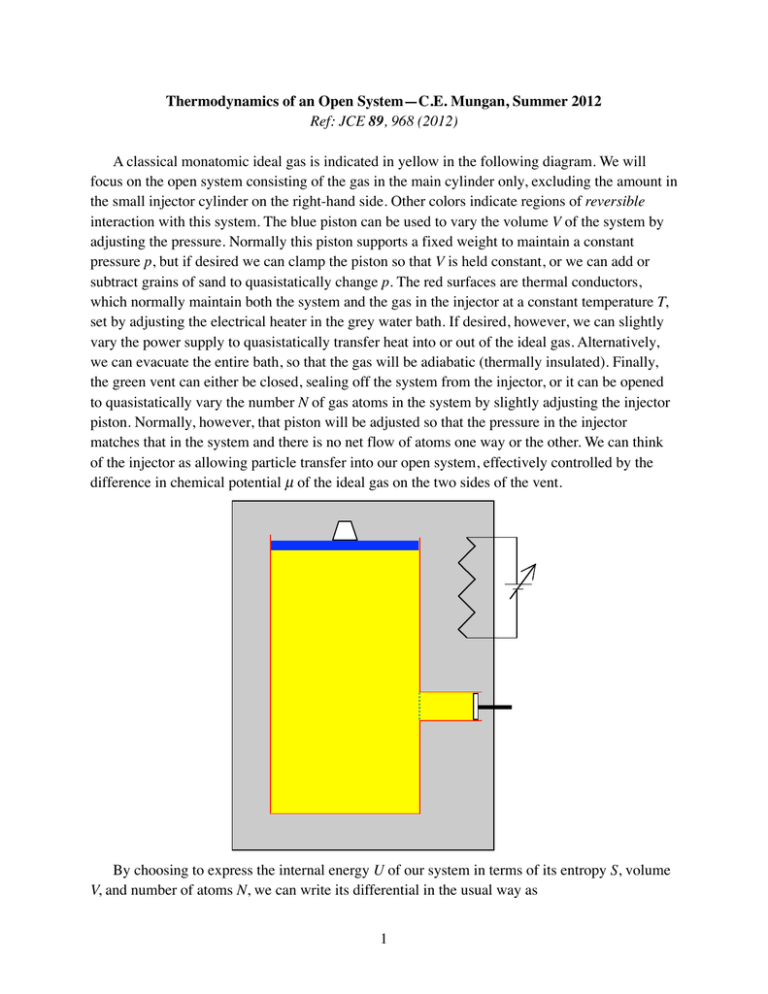
Thermodynamics of an Open System—C.E. Mungan, Summer 2012 Ref: JCE 89, 968 (2012) A classical monatomic ideal gas is indicated in yellow in the following diagram. We will focus on the open system consisting of the gas in the main cylinder only, excluding the amount in the small injector cylinder on the right-hand side. Other colors indicate regions of reversible interaction with this system. The blue piston can be used to vary the volume V of the system by adjusting the pressure. Normally this piston supports a fixed weight to maintain a constant pressure p, but if desired we can clamp the piston so that V is held constant, or we can add or subtract grains of sand to quasistatically change p. The red surfaces are thermal conductors, which normally maintain both the system and the gas in the injector at a constant temperature T, set by adjusting the electrical heater in the grey water bath. If desired, however, we can slightly vary the power supply to quasistatically transfer heat into or out of the ideal gas. Alternatively, we can evacuate the entire bath, so that the gas will be adiabatic (thermally insulated). Finally, the green vent can either be closed, sealing off the system from the injector, or it can be opened to quasistatically vary the number N of gas atoms in the system by slightly adjusting the injector piston. Normally, however, that piston will be adjusted so that the pressure in the injector matches that in the system and there is no net flow of atoms one way or the other. We can think of the injector as allowing particle transfer into our open system, effectively controlled by the difference in chemical potential µ of the ideal gas on the two sides of the vent. By choosing to express the internal energy U of our system in terms of its entropy S, volume V, and number of atoms N, we can write its differential in the usual way as 1 dU = TdS − pdV + µdN . (1) Now in the figure above, we allowed for three kinds of interaction with the system. We will describe them in terms of mechanical work dW at the blue piston, heat dQ through the portions of the red sides that surround our system (i.e., excluding the heat transfer into the injector), and the energy dM associated with matter transfer through the green vent. The goal of the present exercise is to figure out how the three terms on the right-hand side of Eq. (1) relate to these three interaction energies. We will sneak up on the answer by turning on one process at a time. Let’s first evacuate the grey water bath (to shut off dQ) and close the green vent (to shut off dM). It is then clear that both dS and dN are zero. We can however perform a reversible adiabatic compression of our closed system, as described by pV γ = constant where γ = 5 / 3 . In this case we have dW = − pdV . Next, let’s refill the water bath but leave it in its normal state, so our system is now isothermal. This time dU and dN are zero. Now if we quasistatically increase p, we still do positive work dW = − pdV on the system, but it is balanced by an equal and opposite energy transfer out of the gas in the form of a heat flow dQ = TdS . Both dV and dS are negative. Finally we will open the green vent, while leaving the water bath in its normal state at fixed T. This time we will also put the blue piston in its normal state, exerting a fixed pressure p. But we will quasistatically compress the injector piston. It is tempting to simply jump to the conclusion that dM = µdN , dQ = TdS , and dW = − pdV but now we come to the big surprise that this conclusion is wrong! Why don’t you think it over for a minute before reading further and see if you can spot the problem? Actually there’s nothing wrong with dW = − pdV . The really big blooper is dQ = TdS . The heat that flows across the red walls surrounding our system is NOT the only factor that changes the entropy of our system. There is ALSO an entropy flow from the particles entering the system from the injector. Once you realize that’s wrong, then you’ll also agree that dM = µdN must be wrong, because we defined the quantities above such that dU = dQ + dW + dM . (2) [For what it’s worth, I follow Schroeder’s lead and call Eq. (2)—which is a statement of energy conservation—the “first law of thermodynamics.” But I call Eq. (1)—which is merely a mathematical statement of how to take a differential of 3 independent variables, combined with definitions of T, p, and µ in terms of derivatives of U—the “thermodynamic identity for internal energy.” Many people confuse these two equations. But one is physics and one is merely math. I think the present example nicely illustrates the difference.] A clear way to proceed is to actually compute everything of interest, if we push the injector piston all the way in and so transfer all of its contents to our system. Specifically, let’s spell out some initial conditions. Our system initially contains Ni atoms in it, at pressure p, temperature T, and volume Vi = N i kT / p where k is Boltzmann’s constant; meanwhile, the injector starts out with N atoms in it, at pressure p, temperature T, and volume V = NkT / p . The system ends up 2 with N f = N i + N atoms in it, at pressure p, temperature T, and volume Vf = (N i + N )kT / p . Therefore work W = − pΔV = −NkT was done on the system. The system begins with internal energy U i = 3N i kT / 2 and ends up with U f = 3(N i + N )kT / 2 , for a change of ΔU = 3NkT / 2 . For a monatomic classical ideal gas, the entropy is given by the Sackur-Tetrode equation, ⎧⎪ ⎡ V ⎛ 2π mkT ⎞ 3/2 ⎤ S = Nk ⎨ln ⎢ ⎜ ⎟⎠ ⎥ + 2 ⎝ N h ⎢ ⎥⎦ ⎩⎪ ⎣ 5 ⎫⎪ ⎬ 2⎪ ⎭ (3) where m is the atomic mass and h is Planck’s constant, and the chemical potential is ⎡ V ⎛ 2π mkT ⎞ 3/2 ⎤ µ = −kT ln ⎢ ⎜ ⎟⎠ ⎥ . 2 ⎢⎣ N ⎝ h ⎥⎦ (4) Consequently, one finds for the system that ⎧⎪ ⎡ kT ⎛ 2π mkT ⎞ 3/2 ⎤ T ΔS = NkT ⎨ln ⎢ ⎜ ⎟⎠ ⎥ + 2 ⎥⎦ ⎪⎩ ⎢⎣ p ⎝ h 5 ⎫⎪ ⎬ 2⎪ ⎭ (5) and ⎡ kT ⎛ 2π mkT ⎞ 3/2 ⎤ µΔN = −NkT ln ⎢ ⎜ ⎟⎠ ⎥ . 2 ⎝ p h ⎢⎣ ⎥⎦ (6) It follows that ΔU = T ΔS − pΔV + µΔN , thereby verifying Eq. (1). However, all we have actually done is move some gas (with no change in pressure, temperature, or density) from the injector to the main cylinder. No heat transfer across the walls is required to do that, and so Q = 0 . If you want further convincing, consider the entire closed system of the gas in both the main cylinder and injector. We’re then back to our second scenario above—at the end of the first full paragraph after Eq. (1)—where particle number is constant, and work done on the system is balanced by equal and opposite heat transferred out of it. But here the net work is zero (the gas in the injector does negative work on the injector piston, while the gas in the main cylinder does equal and opposite positive work on the blue piston), and thus the heat transfer is also zero. We therefore see that Q is NOT equal to T ΔS . Consequently, M is not equal to µΔN (sometimes called the “chemical work”) but must instead be equal to 5NkT / 2 , according to Eq. (2). Alternatively, we can directly argue that M must equal the change in enthalpy of the system, just as in the familiar experiment where one pushes a gas through a porous plug, ΔH = Δ(U + pV ) . The term pΔV is often called the “flow work” done by the injector piston and transferred across the green vent with the gas. In short, the added gas carries internal energy and entropy per particle, ΔU / N and ΔS / N . When we increase the number of particles in our open system, the energy and entropy increase proportionately. 3


