Problem Set 3 Solutions
advertisement
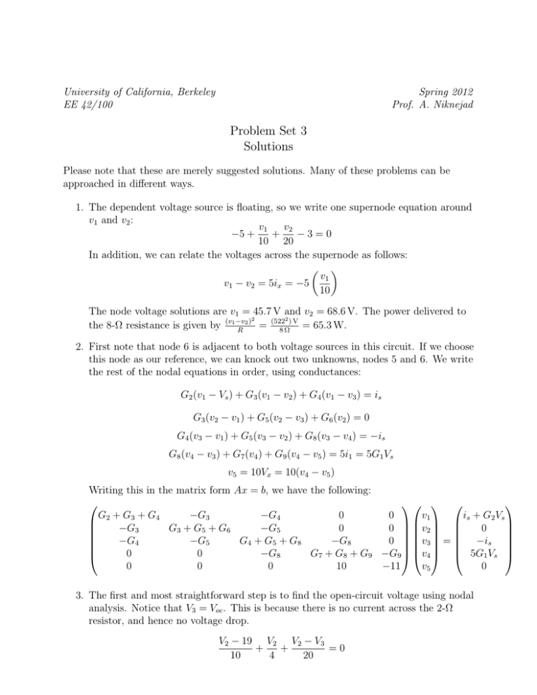
University of California, Berkeley EE 42/100 Spring 2012 Prof. A. Niknejad Problem Set 3 Solutions Please note that these are merely suggested solutions. Many of these problems can be approached in different ways. 1. The dependent voltage source is floating, so we write one supernode equation around v1 and v2 : v2 v1 + −3=0 −5 + 10 20 In addition, we can relate the voltages across the supernode as follows: v1 v1 − v2 = 5ix = −5 10 The node voltage solutions are v1 = 45.7 V and v2 = 68.6 V. The power delivered to 2 2) V 2) the 8-Ω resistance is given by (v1 −v = (522 = 65.3 W. R 8Ω 2. First note that node 6 is adjacent to both voltage sources in this circuit. If we choose this node as our reference, we can knock out two unknowns, nodes 5 and 6. We write the rest of the nodal equations in order, using conductances: G2 (v1 − Vs ) + G3 (v1 − v2 ) + G4 (v1 − v3 ) = is G3 (v2 − v1 ) + G5 (v2 − v3 ) + G6 (v2 ) = 0 G4 (v3 − v1 ) + G5 (v3 − v2 ) + G8 (v3 − v4 ) = −is G8 (v4 − v3 ) + G7 (v4 ) + G9 (v4 − v5 ) = 5i1 = 5G1 Vs v5 = 10Vx = 10(v4 − v5 ) Writing this in the matrix form Ax = b, we have the following: G2 + G3 + G4 −G3 −G4 0 0 v1 is + G2 Vs −G3 G3 + G5 + G6 −G5 0 0 v2 0 −G4 −G5 G4 + G5 + G8 −G8 0 v3 = −is 0 0 −G8 G7 + G8 + G9 −G9 v4 5G1 Vs 0 0 0 10 −11 v5 0 3. The first and most straightforward step is to find the open-circuit voltage using nodal analysis. Notice that V3 = Voc . This is because there is no current across the 2-Ω resistor, and hence no voltage drop. V2 − 19 V2 V2 − V3 + + =0 10 4 20 V3 − V2 V3 − 19 V3 + + = 2Ix = 2 20 5 8 19 − V2 10 The solutions are V2 = 6.94 V and V3 = Voc = VT h = 17.49 V. The next step is to find Isc by shorting the terminals: 5Ω Ix V1 + 10 Ω 20 Ω V2 19 V 2I x 4Ω 2Ω V3 8Ω a I sc b V2 − 19 V2 V2 − V3 + + =0 10 4 20 19 − V2 V3 − V2 V3 − 19 V3 V3 + + + = 2Ix = 2 20 5 8 2 10 The solutions are V2 = 5.71 V and V3 = 7.71 V. Thus, Isc = IN = The final step is RT h = RN = VT h IN V3 2 = 3.86 A. = 4.53 Ω. 4. Since there are four sources, we will consider each one at a time in four different subcircuits. First we will find the equivalent resistance by zeroing out all the sources: 10Ω 20Ω 30Ω 40Ω 50Ω Notice that the 50-Ω resistor is shorted out. The equivalent resistance is Req = RT h = RN = 30||(10 + 20 + 40) = 21 Ω. The next step is to find the Thevénin voltage. We start with the 10 V source. 2 10Ω 20Ω 30Ω 10 V + 40Ω + Voc − 50Ω By voltage divider (and shorting out the 50-Ω resistor): Voc1 = 30 (10 V) = 3 V 10 + 20 + 30 + 40 10Ω 20Ω 7A 30Ω 40Ω + Voc − 50Ω Voc2 is given by Ohm’s law across the 30-Ω resistor. To find the current across it, we can use a current divider between it and the other resistors in series (except for the shorted out 50-Ω): 70 Voc2 = IR = − (7 A) (30 Ω) = −147 V 100 3 10Ω 20Ω 30Ω 40Ω + Voc − 5A 50Ω This analysis is similar to the previous, except now the 40-Ω resistor is in parallel with the others in series (again ignore the 50-Ω). 40 (5 A) (30 Ω) = −60 V Voc3 = IR = − 100 10Ω 20Ω 30Ω 40Ω 5V + + Voc − 50Ω Last step is to deal with the 5 V source. This time the 50-Ω resistor is not shorted out, but we can ignore it if we consider a voltage divider between the 30-Ω resistor and the other ones: Voc4 = − 30 (5 V) = −1.5 V 10 + 20 + 30 + 40 The final step is to sum up all the individual components. Thus, we have V Voc = VT h = −205.5 V. Lastly, we can find IN = RVTThh = −205.5 = −9.79 A. 21 Ω 5. This is a problem calling for the usage of the maximum power transfer theorem. To maximize the power transferred across the load, we need to choose its value such that it is equal to that of the Thévenin resistance as seen by RL . To find it, we can simply zero out the current source and find Req between the two terminals. 4 2 kΩ 4 kΩ R eq 6 kΩ 8 kΩ This is simply given by Req = RT h = RL = (2k + 6k)||(4k + 8k) = 4800 Ω. 6. We notice that this op amp is in negative feedback, so we can apply the summing point constraint: v+ = v− and i+ = i− = 0. Using Ohm’s law, v+ = v− = iS RS . At the output, we again use Ohm’s law and see that iL = Rv+L = iSRRLS . Thus the gain is Gi = iL RS = iS RL 7. We have negative feedback, so we can apply the summing point constraint. So we simply have vO = vS , and the gain is just Gv = 1. 8. The best way to go about this problem is to first find a relationship between vo (t) and vin (t). Notice that because of negative feedback, we have v− = v+ = 1 V. So we can write a simple nodal equation at v− as follows: 1 − vin (t) 1 − vo (t) =0 + 10000 R2 Now we want to satisfy some condition for vo (t), so let’s solve for the output voltage: vo (t) = 1 + R2 R2 (1 − vin (t)) = 1 + (1 − 5 − 3 cos(1000t)) 10000 10000 The condition we want to satisfy is for the DC component of the output to be 0, so we want the constant part to equal 0: 1− 4R2 =0 10000 Solving for this gives us R2 = 2500 Ω. Furthermore, the output simplifies to vo (t) = −0.75 cos(1000t). 9. (a) Again using negative feedback, we can conclude the following nodal voltages by applying the golden rules at the inputs of both op amps: 5 R1 v1 R2 vx R 3 v2 R4 vo v1 v2 Now we write two nodal equations at v1 and v2 . v1 v1 − vx + =0 R1 R2 v2 − vx v2 − vo + =0 R3 R4 Solving for these equations gives us the following relationship: vo = R3 + R4 R4 v2 − (R1 + R2 )v1 R3 R1 R3 In order for this expression to be in the form vo = K(v2 − v1 ), we must have the following constraint: R4 R3 + R4 = (R1 + R2 ) R3 R1 R3 This simplifies to R1 R3 = R2 R4 . (b) If the resistors have 1% precision, then any resistor Ri can have a resistance as high as 1.01Ri or as low as 0.99Ri . Let’s assume that each resistor takes on a value R = Rnom (1 + ∆) where Rnom is the nominal value, and |∆| < 0.01 is the tolerance (positive or negative). Now re-write the expression for the gain as vo = a2 v2 − a1 v1 The a2 coefficient is expanded and then simplified assuming ∆ are small a2 = 1 + R4 (1 + ∆4 ) R4 R4 R40 = 1+ ≈ 1+ (1 + ∆4 )(1 − ∆3 ) ≈ 1 + (1 + ∆4 − ∆3 ) 0 R3 R3 (1 + ∆3 ) R3 R3 Notice that a2 can be written in terms of the ideal gain G = 1 + R4 R3 G−1 a2 = G + (G − 1)(∆4 − ∆3 ) = G 1 + (∆4 − ∆3 ) = G(1 + 2 ) G Likewise, we can expand the coefficient a1 R0 R0 R4 (1 + ∆4 ) a1 = 40 (1 + 20 ) = R3 R1 R3 (1 + ∆3 ) 6 (1 + ∆2 ) R2 1+ (1 + ∆1 ) R1 Note that R2 /R1 = R3 /R4 so we have (1 + ∆4 ) a1 = (1 + ∆3 ) R4 (1 + ∆2 ) + R3 (1 + ∆1 ) Simplifying assuming ∆ are small R4 ∆2 − ∆1 a1 ≈ (1 + ∆4 − ∆3 ) + (1 + ∆2 − ∆1 ) = (1 + ∆4 − ∆3 )G 1 + R3 G or ∆2 − ∆1 a1 ≈ G 1 + ∆4 − ∆3 + = G(1 + 1 ) G For a common-mode input Vc we have vo = a1 Vc − a2 Vc = G(1 + 1 )Vc − G(1 + 2 ) = GVc (1 − 2 ) The common-mode gain is therefore Ac = ∆2 − ∆1 G − 1 vo − (∆4 − ∆3 )) = G(∆4 − ∆3 + Vc G G or Ac = (∆4 − ∆3 ) + ∆2 − ∆1 The worst case is when the gain is maximized, or the errors in the ∆’s conspire to maximize the difference Ac = 4|∆| 7
