XXII. SHOP NOTES A.
advertisement

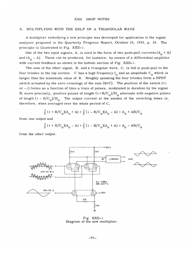
XXII. A. SHOP NOTES MULTIPLYING WITH THE HELP OF A TRIANGULAR WAVE A multiplier embodying a new principle was developed for application in the signal analyzer proposed in the Quarterly Progress Report, October 15, 1953, p. 30. The principle is illustrated in Fig. XXII-1. One of the two input signals, A, is used in the form of two push-pull currents (A and (A 0 - A). + A) These can be produced, for instance, by means of a differential amplifier with current feedback as shown in the bottom section of Fig. XXII-1. The sum of the other signal, four triodes in the top section. B, and a triangular wave, C, is fed in push-pull to the C has a high frequency fo and an amplitude C o which is larger than the maximum value of B. Roughly speaking the four triodes form a DPDT switch actuated by the zero crossings of the sum (B+C). or -1) forms as a function of time a train of pulses, The position of the switch (+1 modulated in duration by the signal B; more precisely, positive pulses of length (1 + B/Co)/2fo alternate with negative pulses of length (1 - B/Co)/2f o . The output current at the anodes of the switching tubes is, therefore, when averaged over the whole period of C, 1 (1 + B/C)(A + A) + 1 (1 - B/C )(A - A) = A - A) + I (1- + A) = A 0 - AB/C + AB/C 0 from one output and 1 (1 + B/C )(A B/Co)(A 0 from the other output. -ZLZ+I7T 125V DC B+C 45V DG A Fig. XXII-1 Diagram of the new multiplier. -91- (XXII. SHOP NOTES) A closer analysis shows that if the switching operations take place in finite times these results are not altered, provided that the tubes are symmetrical and that the switching operations are always completed. shifts in B and in the output. Asymmetries in the tubes result in zero These effects are small, since the signal B is large. The triangular wave can be generated by any standard procedure that satisfies the accuracy requirements in the specified application. the amplitude of C. The relative accuracy improves with In the circuit shown this amplitude can be at most 50 volts peak- to-peak at the grids of the switching tubes. A larger amplitude can be used, provided that limiters are placed before the switching tubes to prevent the flowing of grid current. Since no stringent demands on bandwidth and accuracy had to be met for application in the analyzer, no attempt was made to determine the best performance. An auxiliary frequency of 50 kc/sec was used, but it could probably be increased to 1 Mc/sec without encountering many difficulties, since a square wave of the auxiliary frequency does not occur in the system. Accuracy and zero shift of a few percent were obtained. The band- width of the input signals should not exceed (f /4); or even less when a high accuracy for large values of B/Co is sought. An independently developed multiplier, probably working on a closely related principle, is described by Robert L. Mills, J. Acoust. Soc. Am. 25, 820 (July 1953). F. A. Muller -92-


