S. C. H. Dreicer J. J. McCarthy
advertisement
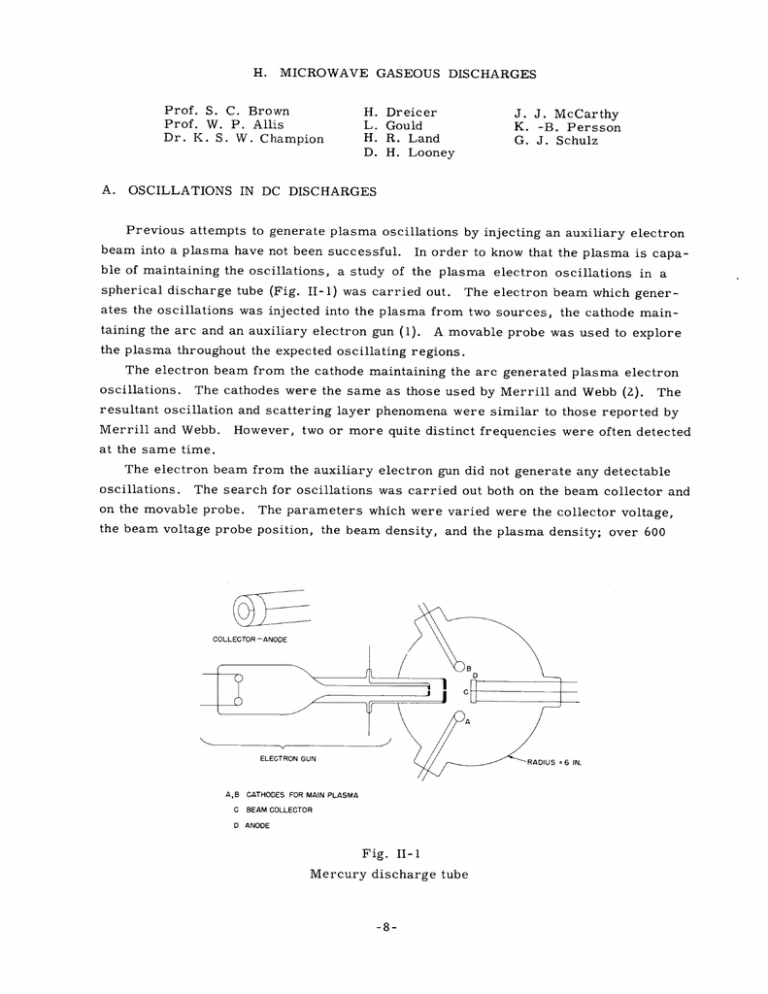
H. Prof. S. MICROWAVE GASEOUS DISCHARGES C. Brown Prof. W. P. Allis Dr. K. S. W. Champion A. H. Dreicer J. J. McCarthy L. Gould H. R. Land D. H. Looney K. -B. Persson G. J. Schulz OSCILLATIONS IN DC DISCHARGES Previous attempts to generate plasma oscillations by injecting an auxiliary electron beam into a plasma have not been successful. In order to know that the plasma is capable of maintaining the oscillations, a study of the plasma electron oscillations in a spherical discharge tube (Fig. II-1) was carried out. The electron beam which generates the oscillations was injected into the plasma from two sources, the cathode maintaining the arc and an auxiliary electron gun (1). A movable probe was used to explore the plasma throughout the expected oscillating regions. The electron beam from the cathode maintaining the arc generated plasma electron oscillations. The cathodes were the same as those used by Merrill and Webb (2). The resultant oscillation and scattering layer phenomena were similar to those reported by Merrill and Webb. However, two or more quite distinct frequencies were often detected at the same time. The electron beam from the auxiliary electron gun did not generate any detectable oscillations. The search for oscillations was carried out both on the beam collector and on the movable probe. The parameters which were varied were the collector voltage, the beam voltage probe position, the beam density, and the plasma density; over 600 A,B CATHODES FOR MAIN PLASMA C BEAM COLLECTOR D ANODE Fig. II-1 Mercury discharge tube -8- (II. combinations were tried. MICROWAVE GASEOUS DISCHARGES) The frequency range covered 400 to 1800 Mc/sec. The plasma of the tube has been shown to be capable of generating oscillations. Since the only electron beam from the gun structure failed to excite oscillations, the difficulty must lie in the injected electron beam itself or its interaction mechanism with the plasma. B. MICROWAVE BREAKDOWN IN HYDROGEN AT HIGH PRESSURES In an earlier report (3) the study of the breakdown of hydrogen at high pressures using a power source at 100 Mc/sec was completed, and the further study of breakdown of hydrogen at high pressures using a microwave source of power was anticipated. source of the microwave high-power is The a type 5607 magnetron (Litton Industries), The magnetic field which is capable of generating 1000 watts of CW microwave power. of the magnetron is produced by a standard water-cooled laboratory electromagnet proThe average magnetic field strength required vided with hollow Armco iron pole pieces. Water cooling is used on the body and the for operation of the magnetron is 2800 gauss. tuning head of the magnetron, output window. and air cooling is used on the cathode terminal and on the This magnetron is tunable from 8. 5 to 12 cm without any difficulty and with only slight changes in power output. from a current-regulated, 5 kv, Anode power for the magnetron is obtained 1 amp, three-phase power supply. Filament power is obtained from a compensated filament supply which acts to maintain a constant filament resistance after the application of anode power, or to remove the anode power when the filament voltage drops below a specified value or is accidently removed. Except for the fact that a 10-cm waveguide is used to couple power from the magnetron and that a waveguide water load is used as a termination on the power divider, the remainder of the experimental apparatus and measuring equipment is similar to that previously used in low-power breakdown experiments. The resonant cavity used in these measurements is constructed of oxygen-free copper and has provisions for an input and a monitor output coupling loop, a viewing window, and cooling rings to maintain a constant temperature. are made of copper and glass Housekeeper coupling loop 3/8 inch in diameter. The coupling loop windows seals and have provisions for taking a Kovar-glass seals cannot be used because they invariably crack when high rf power is used. These seals are heli-arc welded to coupling nipples previously soldered to the cavity. The resonant wavelength of the cavity is 10. 6 cm, its unloaded Q approximately 2000, and the plate separation 1/4 inch, giving a diffusion length of 0. 2 cm. Measurements of breakdown of hydrogen have been made in this cavity up to pressures of 450 mm using hydrogen obtained from a palladium leak. measurements are substantially in agreement -9- The results of these with the data shown in Fig. II-2 of (II. MICROWAVE GASEOUS DISCHARGES) reference 3 even to the departure of the data from the theory at a value p/E of 0. 11. No explanation is given at this time for the deviation between theory and experiment. Before taking any measurements, efforts were made to ascertain that the high-vacuum parts of the vacuum system were thoroughly baked and outgassed and that no leaks were present. The palladium leak was tested before and after the run for any leaks by a helium-leak detector. The pumping pressure of the system was 10 - 8 mm Hg, and the holding pressure after several hours was between 5 x 10 C. 7 and 7 x 10 - 7 mm Hg. ELECTRON COLLISION CROSS SECTION Measurements of Or/" i , the ratio of the real part of the electron conductivity to the imaginary part, and the electron density were obtained as a function of time in the afterglow of a helium pulsed discharge. The density decay curves yielded values of the ambipolar diffusion coefficient which were more than 20 percent higher than those previously reported. This discrepancy is believed due to the presence of oxygen molecules, which causes an attachment process in addition to the dominating diffusion process. Oxygen impurities of the order of one part in 104 or 105 can produce the phenomenon. In addition, at pressures above 15 mm Hg the density decay curves gave straight lines when the reciprocal density was plotted as a function of time. Measurements of -r/ i as a function of time yielded curves which varied about 10 percent over the decay time. In general, the values of -r /a i appeared to be a function of gas purity. The origin of these effects is questionable; hence, it was necessary to make provisions for producing pure helium and to revise the microwave technique to ensure reproducibility. A new method of measuring r /ai was developed. If the ratio of the power input to the power output of a resonant cavity is plotted as a function of the square of the difference between the measuring frequency and the cavity resonant frequency, a straight line is obtained. The slope of this line yields the cavity characteristics. r/ai can be obtained from a comparison of the measurements with and without a plasma. The advan- tage of the technique is that a null method is utilized, and hence the necessity for taking standing-wave measurements is eliminated. The reproducibility of the data with the new method has been within ±2 percent. In addition, a vacuum system with no stopcocks has been constructed, and pure helium has been produced by allowing liquid helium to diffuse through a fritted glass filter into the vacuum system. The new helium gives decay curves which show a large helium metastable production. At pressures above 15 mm Hg the production of electrons by metastable-mestable collision appears to be a dominant mechanism throughout the afterglow. obtained previously at the higher pressures are no longer present, The curves indicating the important role that minute amounts of impurities play in determining the afterglow characteristics. It was difficult to obtain data of a r/o -10- i because of the instability of the (II. MICROWAVE GASEOUS DISCHARGES) Therefore, before further measure- discharge characteristics with the pure helium. ments can be taken, it will be necessary to make provisions for stabilizing the discharge. D. HIGH-DENSITY MICROWAVE GAS DISCHARGES High-density discharges are of considerable interest at the present time for several reasons. Consequently, a program has been started to investigate high-density micro- wave discharges. Such discharges require operating under conditions above those for plasma resonance. Plasma resonance, of course, occurs in a gas discharge when the dielectric constant 4Trne 2 2 mw becomes zero in the region considered. collisions are appreciable, nomena is the same. ) (For a medium of limited extent and in which this formula is not exact, but the general nature of the phe- The condition for resonance reduces to n 2 = const. 2 Thus, if a discharge is above plasma resonance at one frequency, it will be at resonance for some particular higher frequency. For this reason, the discharges are being pro- duced by 100-Mc waves and are being probed by low-power radiation at about 3000 Mc. We plan to apply a technique first used by Makinson et al. (4) and further developed by Sayers (5) for investigating dc discharges: the higher frequency is swept until the value for plasma resonance is obtained, and then the corresponding electron density is calculated. By such means it is possible to investigate discharges above plasma resonance. Because of the high power necessary to produce the required densities, charges are pulsed. the dis- This reduces problems caused by heating and the liberation of gas impurities from hot surfaces. Pulses up to 2 msec in length are used to ensure that the discharge reaches steady-state conditions. The gas being used is hydrogen. References 1. Quarterly Progress Report, Research Laboratory of Electronics, 1953 2. Harrison J. 3. Quarterly Progress Report, Research Laboratory of Electronics, 1952, p. 10 4. R. E. B. Makinson, P. C. Thonemann, Soc. Lond. B64, 665, 1951 5. Private Communication from J. Merrill, Harold W. Webb: Phys. Rev. Sayers, -11- 55, R. B. King, J. 1952 M. I. T. Jan. 15, 1191, 1939 M.I.T. V. Ramsey: April 15, Proc. Phys.
