IV. LOW TEMPERATURE PHYSICS R. P.
advertisement
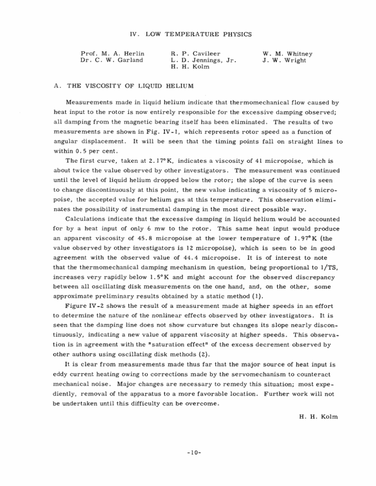
IV. Prof. M. A. Herlin Dr. C. W. Garland A. LOW TEMPERATURE PHYSICS R. P. Cavileer L. D. Jennings, Jr. H. H. Kolm W. M. Whitney J. W. Wright THE VISCOSITY OF LIQUID HELIUM Measurements made in liquid helium indicate that thermomechanical flow caused by heat input to the rotor is now entirely responsible for the excessive damping observed; all damping from the magnetic bearing itself has been eliminated. measurements are shown in Fig. IV-1, angular displacement. The results of two which represents rotor speed as a function of It will be seen that the timing points fall on straight lines to within 0.5 per cent. The first curve, taken at 2. 170 K, indicates a viscosity of 41 micropoise, which is about twice the value observed by other investigators. The measurement was continued until the level of liquid helium dropped below the rotor; the slope of the curve is seen to change discontinuously at this point, the new value indicating a viscosity of 5 micropoise, the accepted value for helium gas at this temperature. This observation elimi- nates the possibility of instrumental damping in the most direct possible way. Calculations indicate that the excessive damping in liquid helium would be accounted for by a heat input of only 6 mw to the rotor. This same heat input would produce an apparent viscosity of 45.8 micropoise at the lower temperature value observed by other investigators is 12 micropoise), which is agreement with the observed value of 44.4 micropoise. It is of 1.970K (the seen to be in good of interest to note that the thermomechanical damping mechanism in question, being proportional to 1/TS, increases very rapidly below 1.50K and might account for the observed discrepancy between all oscillating disk measurements on the one hand, and, on the other, some approximate preliminary results obtained by a static method (1). Figure IV-2 shows the result of a measurement made at higher speeds in an effort to determine the nature of the nonlinear effects observed by other investigators. It is seen that the damping line does not show curvature but changes its slope nearly discontinuously, indicating a new value of apparent viscosity at higher speeds. This observa- tion is in agreement with the "saturation effect" of the excess decrement observed by other authors using oscillating disk methods (2). It is clear from measurements made thus far that the major source of heat input is eddy current heating owing to corrections made by the servomechanism to counteract mechanical noise. Major changes are necessary to remedy this situation; most expe- diently, removal of the apparatus to a more favorable location. Further work will not be undertaken until this difficulty can be overcome. H. H. Kolm -10- (0.101CM/SE z cn z 4 a 8/27 RADIANS (REVOLUTIONS) Fig. IV-1 The observed decay of rotation in helium II and in gaseous helium at two temperatures. 150 (1.52 CM/SEC) 140 ,8 = 0.0298 MINUTE -' (63 .3p) 130 $=0.0172 6 6 (3 . 0 I 10 I I 20 30 40 8/2r RADIANS (REVOLUTIONS) MINUTE -I p) I 50 I 60 Fig. IV-2 The decay of rotation in helium II at higher speeds. -11- (IV. LOW TEMPERATURE PHYSICS) References 1. J. G. Daunt and R. S. Smith, Revs. Modern Phys. 26, 176 (April 1954). 2. A. C. Hollis-Hallet, Proc. Roy. Soc. (London) A210, 404 (1952). B. HALL-EFFECT AND MAGNETO-RESISTANCE RESISTANCE MINIMUM METALS: EFFECT MEASUREMENTS IN DISCUSSION OF FEASIBILITY The "resistance minimum" effect in magnesium has been investigated through measurement of electric and thermal conductivities and thermoelectric power. Electric conductivity has been investigated through a mutual-inductance technique so that bulk samples could be used. In order to separate effects of the mean free path and the electron energy level density, it is desirable to measure the Hall effect. Also, the magnetoresistance effect has already proved enlightening in other resistance minimum metals. Because of the high electrical conductivity, the conventional Hall-effect measurement method requires fine films of metal to provide sufficiently high Hall emfs, and the metallurgical state of the film is difficult to control. It is desirable, therefore, to devise a mutual-inductance method for this measurement, also. Mutual inductance techniques for measurements on magnetic salts have been improved in this laboratory by L. D. Jennings and the writer. It is now possible to apply these methods to Halleffect measurements with adequate accuracy. In essence the mutual inductance as a function of applied dc magnetic field for two different coil configurations (described below) determines both the magneto-resistance and Hall coefficients. For mathematical simplicity a spherical sample is chosen. In the first configuration, the axes of the primary and secondary coils are aligned parallel to the applied dc magnetic field. The Hall effect is then radial and contributes nothing to the emf induced in the secondary coil. The effect of unavoidable misalignment of the secondary coil has been computed and is unimportant. This is essentially, then, the experiment of Rorschach and Herlin; the conductivity is obtained as a function of magnetic field. In the second configuration the primary and secondary coils and the magnetic field are mutually perpendicular. The circulating currents induced by the primary field are diverted by the dc field, producing an induced emf in the secondary. In the conventional Hall experiment, the current lines are constrained to flow parallel to edges of the metal by the Hall field caused by edge charges. In this method the current is actually diverted, and the change in mutual inductance gives the product of the conductivity and the Hall constant. The conductivity measurement is therefore a necessary companion experiment. -12- (IV. In the second configuration, LOW TEMPERATURE PHYSICS) the alignment of the primary with respect to the secondary is critical, but the alignment of either coil with respect to the magnetic field is not. The effect of primary-secondary misalignment may be corrected by rotation of the dc field ninety degrees into the direction of the primary. The mutual inductance thus measured will be that without the Hall effect and will constitute the major correction due to misalignment. With realizable coils, the anticipated change of mutual inductance over the whole range of magnetic field up to 10, 000 gauss is of the order of 0. 1 to 1 microhenry. The bridge to be used is sensitive to 0.001 microhenry, so that a precision of one per cent should prevail. J. -13- W. Wright
