Cold Load Pickup IEEE PES PSRC Working group D1
advertisement

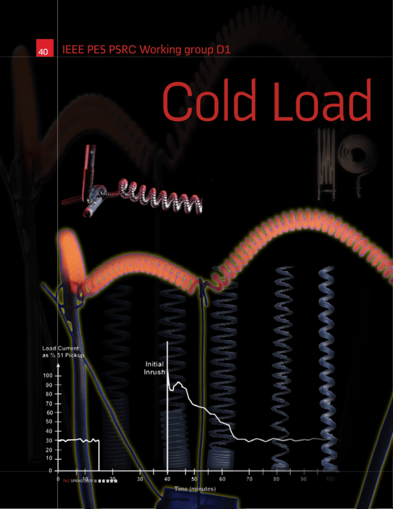
40 IEEE PES PSRC Working group D1 Cold Load PAC.SPRING.2009 by IEEE PES PSRC Working group D1 41 D1 Working Group Report Cold Load Pickup Protection Pickup This article is a summary of a report to the Line Protection Subcommittee of the Power System Relay Committee of the IEEE Power & Energy Society, prepared by working group D1. It describes cold load pickup and inrush problems as they affect p r o t e c t i ve r e l ay i n g applications on dist r ibut ion feeder circuits and provides guidance for protective system applications. The complete report can be downloaded from: www. pes-psrc.org/Reports/ Usually when a distribution circuit is restored after an extended outage, the demand is greater than before the outage. Attempting to pick up this load can be problematic because the initial load demand after an outage can exceed the load demand that would have been observed at any time before the outage. This phenomenon is referred to as cold load pickup because the power supply has been unavailable for a period of time so that the load has reached a “cold” state before being re-energized. Since in most cases cold load pickup current is greater than pre-outage current, cold load pickup affects fault detection. That is, protective relays can misinterpret the cold load pickup condition as a fault and initiate de-energization of an unfaulted circuit. There are many factors that determine the magnitude and duration of cold load pickup. These include: outage duration, types of connected load, weather, restoration mode, outage causes, the presence of distributed generation and/or automatic transfer schemes, time of day, and load level. Each of these is addressed in this report. The goal of this article is to provide an understanding of the cold load pickup phenomenon and the options available with modern protective relays so improvements in the protection of distribution circuits can be achieved. Cold Load Pickup is the phenomenon that takes place when a distribution circuit PAC.SPRING.2009 Cold Load Pickup Protection 42 Cold load pickup needs to be included is re-energized following an extended outage of that circuit. Cold load pickup is a composite of two conditions: inrush and loss of load diversity. The magnitude of cold load pickup current is a combination of non-diverse cyclic load current, continuously operating load current, transformer magnetizing current, capacitor inrush current, etc. The combination can result in current levels that are significantly higher than normal peak load levels. Cold load pickup current can be high enough to cause instantaneous overcurrent and/or time overcurrent relays to operate. Cold load pickup is primarily an overcurrent condition. If degraded voltage is also a concern, then the application of voltage sensitive relays should also be considered. Factors Influencing Cold Load Pickup Load types can be categorized in many ways. From the perspective of cold-load pickup, the most important load characteristics are initial inrush upon re-energization and sustained inrush in excess of normal continuous load. Most types of load incur an initial inrush upon energization. The most common load types are described in the report: Lighting load consisting primarily of filament and gas vapor lamps Motors used for many residential, commercial, and industrial applications. Electric resistance heating used for water, space and process heating applications Magnetic loads such as transformers and voltage regulators Other factors that impact the cold load pickup considered in the report are: Nature of the outage, size and severity of the affected area Weather related factors that directly impact the amount of cold load pickup following an outage Daily profile of the load on a circuit varies with the type of load (residential, commercial, agricultural or industrial), season, region, and day of week Duration of an outage Restoration process Power factor correction and voltage support capacitors Distributed electrical power sources located electrically close to the customer loads Estimating Load Levels Following an Outage In order to determine load levels following a distribution circuit outage, load characteristics and the percent of each type of load connected to each distribution circuit must be estimated. Generally, load levels are estimated for peak load conditions, that is, peak winter heating load and/or peak summer cooling load. After load types are identified, diversity factors are assigned for each load type. If it is anticipated that one-half of all connected space heaters will be operating during peak load conditions, then a diversity factor of 50% would be assigned to space heaters. When calculating cold load pickup the percent of each type of load should be divided by the diversity factor to determine the cold load pickup value, as all space heaters may be energized when power is restored. In Table 1 these factors are illustrated for a hypothetical circuit with predominately residential type of loads during heating season. After cold load pickup factors have been established, total circuit current and time dependent current variations need to be evaluated. In general, four specific time intervals need to be considered: initial circuit energization which includes inrush current to all connected loads, 0.2 second inrush which characterizes circuit load as miscellaneous small motors are transitioning from starting to running, 2.0 seconds at which point steady state current has been reached, and 15 minute sustained load which characterizes circuit load before load diversity begins to recover. The inrush magnitude and duration varies with the type of load as summarized in Table1. Values in the table are multiples of the running current for each load type. Total circuit current should be determined algebraically as inrush to incandescent lights and heaters will be high 11 12 as one of the considerations Cold Load 1200 when 1000 Peak Current = 960 Amperes protective 800 are selected Amperes relay set-points 600 400 for distribution Chart 200 Load when deenergized = 144 Amperes feeder protection. OSC Stop 0.01 0.1 PAC.SPRING.2009 0 1 10 67Min Later 195 Amperes 100 1000 10000 Electric stove by IEEE PES PSRC Working group D1 43 power factor whereas motor starting current with be low power factor. Allowance can be made for reduced voltage, if during cold load pickup, distribution circuit voltage may sag. The voltage recovery inrush described in Clause 2.7 can result in tripping non-faulted feeders that are connected to the same source transformer as a faulted feeder. Figure 4 demonstrates the sympathetic tripping of an example feeder. While this condition generally involves the circuit unbalance and ground relaying, other case studies have shown sustained phase currents over 1000 amps for similar instances and similar tripping has been experienced, especially where low set instantaneous phase relays have been used as a part of fuse saving schemes. The probability of experiencing sympathetic tripping can be reduced by the following steps, either collectively or individually: Setting the instantaneous overcurrent relays higher than the expected cold load pickup current and higher than the current experienced during a sympathetic trip event Implementing alternate setting groups on non-faulted feeders in conjunction with faults that occur on other feeders served by the same substation transformer. The detection of this condition can use information from the local feeder and 1) other feeders on the bus, 2) the voltage on the bus, or 3) overcurrent information from the source transformer Protection System Application Considerations Relays are used pr imar ily to detect faults on distribution systems and initiate operation of breakers to clear faults. Overcurrent relays, both time overcurrent and instantaneous, are predominantly used. Relays are set to coordinate with down stream devices whether they are fuses, reclosers, or other relays. At the same time, substation feeder relays are set to coordinate with upstream relays and fuses. Since currents resulting from cold load pickup can be much greater than load current, the potential for overcurrent relays to operate during cold load pickup is great. What can be done to accommodate cold load pickup currents is limited by the type of relay being applied. The following discussion reviews what can be done to accommodate cold load pickup with these relay types: electromechanical, solid state, and microprocessor. Electromechanical Relays: Three operat ing characteristics define electromechanical time overcurrent relays: the time overcurrent characteristic curve, the pick up current, and the time dial. The relay is set by adjusting mechanical devices, such as springs and set-screws. The settings are fixed and not able to be changed by automatic methods. Consideration for cold load pickup should be taken into account at the time of the protective system design and settings determination. This consideration should involve all three characteristics of the relay. If the relay package includes an instantaneous element, the element can be disabled or blocked for a period of time The methodology in this report assumes that an outage of sufficient duration has occurred under maximum load. before and during load energization. This is done in order to permit ride through during the inrush part of the cold load pickup. Solid State Relays: Solid state relays contain the same characteristics as the electromechanical relays, but predominantly use solid state electronics instead of electromechanical devices. Additional functionality is typical and includes such items as multiple time overcurrent characteristic curves. In some applications, rudimentary adaptive schemes have been employed. An example included a panel switch that enabled circuitry to double the current pickup as long as the switch was held in the closed position. Microprocessor Relays: Such relays emulate the characteristics of the electromechanical and solid state relays, but use microprocessor based technology. Functionality is dramatically increased which allows multiple setting aspects: Timers to enable cold load pickup logic after the breaker has been open for a defined period of time Separate phase and ground overcurrent element multipliers to individually adjust the phase and ground overcurrent pickup while the cold load pickup logic is enabled 13 Iced power lines Working Group: Dean Miller, Chairman; Tony Sleva, Vice Chairman; Alex Apostolov; Randy Crellin; Raluca Lascu; George Bartok; Al Darlington; Don Lukach; Ken Behrendt; Fred Friend; Mike Meisinger; John Boyle; Rafael Garcia; Tony Napikoski; Mark Carpenter; Roger Hedding; James Niemira; Patrick Carroll; Bill Kennedy; Don Parker; Phil Waudby When a feeder is restored after an extended outage, the load can exceed the normal feeder load until normal load cycling is re-established. Photo courtesy of Robert Lawton PAC.SPRING.2009 44 Protection table 1 Cold load pickup model Current detectors to sense when the cold load pickup phase and ground currents subside to below normal overcurrent pickup settings, thereby making is possible to automatically disable cold load pickup logic and restore normal overcurrent settings Timers to override the automatic reset in the event that the cold load pickup current includes a fault below the adjusted sensitivity of the overcurrent elements The capability to either block the instantaneous element or raise the time overcurrent pickup setting for a user selectable or adaptive period of time after the breaker is initially closed after lockout or on detection of inrush New setting groups can be selected to temporarily change settings during a feeder re-energization Multiple overcurrent element settings that can be switched in or out of service without disabling protection Torque-control logic to change the pickup of the overcurrent element(s) without shifting the time-current curve However, the expansion in functionality increases the complexity of settings and the risk of either inadvertent operations or the failure to operate. For example, changing setting groups may not be the best practice if doing so momentarily disables protection. Also, shifting the time-overcurrent curve may not be desirable if coordination is impacted. Distribution Feeder Recloser Operation: When service is restored after a prolonged outage, the cold load pickup current may cause reclosers to operate in a distribution system. The random operation of single phase reclosers can cause a significant rise in residual currents in feeder breakers and neutral currents in substation transformers. Reclosers may operate on both “fast” and “delayed” trip curves driving the reclosers to “lockout”. Under these conditions the reclosers will need to be closed manually to restore the load. Depending on the magnitude of the inrush current and the setting of the “delayed” recloser trip curves, the recloser may operate only on the “fast” curve and not operate on the “delayed” curve. This will result in the reclosers returning to a “closed state” after one or two trip operations on the “fast” curves. Relays monitoring the transformer and feeder neutral current must be set with a high enough pickup and/or sufficient time delay to ride through the unbalance cold load pickup currents caused by the random operation of the single phase line reclosers if this type of fault interrupting device is applied on the circuit. Automated Distribution Feeder Segmentation: Where reclosers and automated sectionalizing switches have been installed out on feeders, it is possible to automatically recover cold load incrementally if cold load pickup is problematic. This strategy is implemented by simply opening feeder mounted devices automatically during conditions that produce cold load pickup conditions. These devices then either close automatically, or via SCADA, at an appropriate time after being reenergized and after establishing stable system voltage. As with other cold load pickup considerations, several factors may govern the determination of the time interval for automatically closing an intermediate feeder device after it is reenergized. These factors are generally combined to ensure that the operating state of active upstream protection can accommodate the load profile added by the intermediate feeder device without tripping. 14 15 Multiple of Steady State Current/Time Interval Load Type Initial 0.2 sec. 2 sec. Cold Load Pickup Area lighting Resistance space heaters Heat pumps Heat pumps resistance heaters Air conditioner Miscellaneous small motors Distributed generation Loads (alternative power sources) Other loads Cold load pickup needs to be addressed on a feeder specific basis. 15 2-8 1 5-8 1 5-8 5-8 1 1 1 1 1 5-8 1 1 1 1 1 1 1 1 1 1 1 1 5-8 1 1 1 1 Sympathetic trip 1600 1500 1400 1300 1200 1100 1000 900 800 700 600 500 400 300 200 100 0 600 Amperes Bus Volts 16000 15000 14000 13000 12000 11000 10000 9000 8000 7000 6000 5000 4000 3000 2000 1000 0 0 Tornado 100 VA PAC.SPRING.2009 200 300 Cycles VB 400 VC 500 Fdr 2953 Ir Photo courtesy of Justin Hobson


