New Textiles Designed for Anti-Radar Camouflage
advertisement
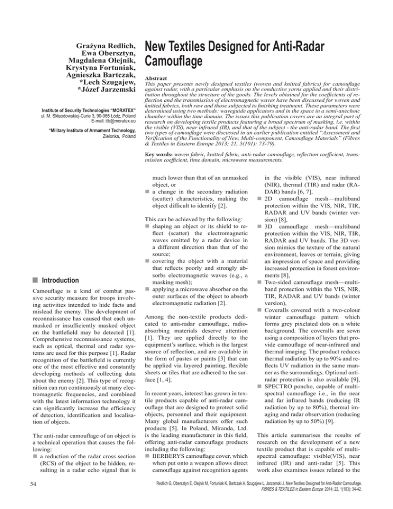
Grażyna Redlich, Ewa Obersztyn, Magdalena Olejnik, Krystyna Fortuniak, Agnieszka Bartczak, *Lech Szugajew, *Józef Jarzemski Institute of Security Technologies “MORATEX” ul. M. Skłaodowskiej-Curie 3, 90-965 Łódź, Poland E-mail: itb@moratex.eu *Military Institute of Armament Technology, Zielonka, Poland New Textiles Designed for Anti-Radar Camouflage Abstract This paper presents newly designed textiles (woven and knitted fabrics) for camouflage against radar, with a particular emphasis on the conductive yarns applied and their distribution throughout the structure of the goods. The levels obtained for the coefficients of reflection and the transmission of electromagnetic waves have been discussed for woven and knitted fabrics, both raw and those subjected to finishing treatment. These parameters were determined using two methods: waveguide applicators and in the space in a semi-anechoic chamber within the time domain. The issues this publication covers are an integral part of research on developing textile products featuring a broad spectrum of masking, i.e. within the visible (VIS), near infrared (IR), and that of the subject - the anti-radar band. The first two types of camouflage were discussed in an earlier publication entitled “Assessment and Verification of the Functionality of New, Multi‑component, Camouflage Materials” (Fibres & Textiles in Eastern Europe 2013; 21, 5(101): 73-79). Key words: woven fabric, knitted fabric, anti-radar camouflage, reflection coefficient, transmission coefficient, time domain, microwave measurements. much lower than that of an unmasked object, or n a change in the secondary radiation (scatter) characteristics, making the object difficult to identify [2]. nIntroduction Camouflage is a kind of combat passive security measure for troops involving activities intended to hide facts and mislead the enemy. The development of reconnaissance has caused that each unmasked or insufficiently masked object on the battlefield may be detected [1]. Comprehensive reconnaissance systems, such as optical, thermal and radar systems are used for this purpose [1]. Radar recognition of the battlefield is currently one of the most effective and constantly developing methods of collecting data about the enemy [2]. This type of recognition can run continuously at many electromagnetic frequencies, and combined with the latest information technology it can significantly increase the efficiency of detection, identification and localisation of objects. The anti-radar camouflage of an object is a technical operation that causes the following: n a reduction of the radar cross section (RCS) of the object to be hidden, resulting in a radar echo signal that is 34 This can be achieved by the following: n shaping an object or its shield to reflect (scatter) the electromagnetic waves emitted by a radar device in a different direction than that of the source; n covering the object with a material that reflects poorly and strongly absorbs electromagnetic waves (e.g., a masking mesh); n applying a microwave absorber on the outer surfaces of the object to absorb electromagnetic radiation [2]. Among the non-textile products dedicated to anti-radar camouflage, radioabsorbing materials deserve attention [1]. They are applied directly to the equipment’s surface, which is the largest source of reflection, and are available in the form of pastes or paints [3] that can be applied via layered painting, flexible sheets or tiles that are adhered to the surface [1, 4]. In recent years, interest has grown in textile products capable of anti-radar camouflage that are designed to protect solid objects, personnel and their equipment. Many global manufacturers offer such products [5]. In Poland, Miranda, Ltd. is the leading manufacturer in this field, offering anti-radar camouflage products including the following: n BERBERYS camouflage cover, which when put onto a weapon allows direct camouflage against recognition agents in the visible (VIS), near infrared (NIR), thermal (TIR) and radar (RADAR) bands [6, 7], n 2D camouflage mesh—multiband protection within the VIS, NIR, TIR, RADAR and UV bands (winter version) [8], n 3D camouflage mesh—multiband protection within the VIS, NIR, TIR, RADAR and UV bands. The 3D version mimics the texture of the natural environment, leaves or terrain, giving an impression of space and providing increased protection in forest environments [8], n Two-sided camouflage mesh—multiband protection within the VIS, NIR, TIR, RADAR and UV bands (winter version), nCoveralls covered with a two-colour winter camouflage pattern which forms grey pixelated dots on a white background. The coveralls are sewn using a composition of layers that provide camouflage of near-infrared and thermal imaging. The product reduces thermal radiation by up to 90% and reflects UV radiation in the same manner as the surroundings. Optional antiradar protection is also available [9], n SPECTRO poncho, capable of multispectral camouflage i.e., in the near and far infrared bands (reducing IR radiation by up to 80%), thermal imaging and radar observation (reducing radiation by up to 50%) [9]. This article summarises the results of research on the development of a new textile product that is capable of multispectral camouflage: visible(VIS), near infrared (IR) and anti-radar [5]. This work also examines issues related to the Redlich G, Obersztyn E, Olejnik M, Fortuniak K, Bartczak A, Szugajew L, Jarzemski J. New Textiles Designed for Anti-Radar Camouflage. FIBRES & TEXTILES in Eastern Europe 2014; 22, 1(103): 34-42. project for developing anti-radar camouflage. The decision was made that the new textile structures developed would be designed mainly for outer clothing, blankets and capes, as well as covers for personal equipment. Additionally, an assumption was made that the camouflage properties should be obtained by a specially selected structure of the fabrics and not covering them by special pastes and paints. Table 1. Examples of the woven fabrics of various shares of metal in yarns developed – the characteristics; Symbols: “z”—basic yarn, “k”—conductive yarn. Code of fabric Warp T5 n textured polyester yarn dtex 84 f36×2 (white) n textured polyester yarn dtex 84f36×2 (black) n mixed yarn of staple fibres Nm 50/2 (40 tex), (70% PES/30% steel) n textured polyester yarn dtex 167 f96 (white), mixed yarn of staple fibres n yarns Nm 50/2 (40 tex), (70% PES/30% steel) 1/1 T6 n textured polyester yarn dtex 167 f96 (white) n mixed yarn of staple fibres Nm 50/1 (20 tex) (PES 95%/5% steel) 2/2 Z n Subject of research n textured polyester yarn dtex 84 f36×2 (white) n textured polyester yarn dtex 84 f36×2 (black) n mixed yarn of staple fibres Nm 50/1 (20 tex) (PES 95%/5% steel) This publication discusses new textile structures (woven and knitted) capable of anti-radar camouflage. Both the raw materials and those subjected to finishing treatments are examined. T7 n textured polyester yarn dtex 84 f36×2 (white) n textured polyester yarn dtex 84 f36×2 (black). n mixed yarn of staple fibres Nm 50/2 (40 tex) (95% PES/5% steel) n textured polyester yarn dtex 84 f36×2 (white) n mixed yarn of staple fibres Nm 50/2 (40 tex) (95% PES/5% steel) 2/2Z 3z+1k T8 n textured polyester yarn dtex 84 f36×2 (white) n textured polyester yarn dtex 84f36×2 (black) n mixed yarn of staple fibres Nm 50/1 (20 tex), (80% PES/20% steel) n textured polyester yarn dtex 167 f96 (white) n mixed yarn of staple fibres Nm 50/1 (20 tex), (80% PES/20% steel) 2/2 Z 7z+1k T9 n textured polyester yarn dtex 84 f36×2 (white) n textured polyester yarn dtex 84 f36×2 (black) n mixed yarn of staple fibres Nm 50/1 (20 tex) (PES 95%/5% steel) n textured polyester yarn dtex 167 f96 (white) n mixed yarn of staple fibres Nm 50/1 (20 tex), (PES 95%/5% steel) 2/2 Z Woven fabrics The study included textiles (raw and finished) manufactured with the following yarns: n polyester (basis), n conductive, i.e., polyester spun dyed with soot and polyester with steel fibres added at various rates. The individual variants of the woven fabrics differed in their weave and distribution of conductive threads, as indicated in Table 1. Knitted fabrics The research covered knitted fabrics (both raw and finished) made of the following yarns: n polyester (basis), n polyester with additional steel fibres added at various rates. The knitted fabrics differed in their weave and distribution of conductive threads as indicated in Table 2. By changing the structure of the knitted fabrics, the metal fibres became oriented in different directions in those products as follows: n in knitted fabrics D1 and D2, the metal fibres are arranged evenly within the structure of the products, but their share and fill of knitted fabrics are very small, n in knitted fabrics D3 and D6, the metal fibres are arranged evenly throughout the structure of the products, forming symmetric spots, n in knitted fabrics D4, D7 and D8, the metal fibres are arranged in visible stripes running along the length of the product. FIBRES & TEXTILES in Eastern Europe 2014, Vol. 22, No. 1(103) Weft Weave Picking repeat 7z+1k 3z+1k 5z+1k Table 2. Examples of knitted fabrics of various shares of metal in yarns developed – the characteristics. Code of knitted fabric Composition Type of knitted fabric Fill D1 textured polyester yarn 300/96 dtex warp plied with mixed yarns warp-knitted on the basis of of staple fibres Nm 50/2 (40 tex) a weave—a tulle (95% PES & 5% steel) less than 40% D2 textured polyester yarn 300/96 dtex warp plied with mixed yarns warp-knitted on the basis of Nm 50/2 (40 tex) (70% PES & a weave—a tulle 30% steel) less than 40% D3 mixed yarns of staple fibres, Nm 50/1 (20 tex) & Nm 50/2 (40 tex), composition: 95% PES & 5% INOX metal fibres mesh fabric with a rectangular a-jour D4 mixed yarns of staple fibres, Nm 50/1 (20 tex) & Nm 50/2 (40 tex), composition: 95% PES & 5% INOX metal fibres mesh fabric with a hexagonal a-jour D6 textured polyester yarn 300/96 dtex warp plied with mixed yarns wale based on a fancy tricot with of staple fibres Nm 50/2 (40 tex) rectangular mesh (70% PES & 30% steel) ~45% D7 textured polyester yarn 300/96 dtex warp plied with mixed yarns mesh fabric with a hexagonal of staple fibres Nm 50/2 (40 tex) a-jour (95% PES & 5% steel) less than 40% D8 textured polyester yarn 300/96 dtex warp plied with mixed yarns warp-knitted on the basis of of staple fibres Nm 50/2 (40 tex) a weave—a tulle (70% PES & 30% steel) less than 40% n Research methodologies The usability of the textile designs developed for anti-radar camouflage was ~45%. less than 40% assessed at the Radar and Command Systems, Electronic Warfare and Microwave Technology Laboratory, at the Military Institute of Armament Technology in 35 man wearing a suit of the material selected made on a pilot scale. POS_Z BLANK SWEEP OUT/IN Waveguide applicator method STOP SWEEP HPIB A B R RF OUT SYNTEZER SWEEPER HP 83640A SCALAR NETWORK ANALIZER HP8757D TESTED SAMPLE DETEKTOR 11664A This study concerned the measurement of reflectance, transmission and absorption within the frequency range in which most battlefield radars operate, from 8.0 up to 18 GHz. When using waveguide applicators, the transmission rate is determined from a single signal passed through the test material, which means that the signal value is measured behind the material being tested. We obtain information on how much of the signal was suppressed. The apparatus depicted in Figure 2 was used to obtain reflectance measurements. APPLICATION FOR TRANSMISION MEASUREMENT The “Time Domain” method PRINTER The measurement facility shown in Figure 3 was used to examine the reflection and transmission properties in a semianechoic chamber with a PNAX vector analyser from Agilent, USA as the measuring device, operating in the “Time Domain” mode. This setup allowed the signal to be analysed as a function of time. The research was conducted in the frequency band of 18 ± 500 MHz for three samples settings - 0°, 15° and 30° to the direction of the signal transmitted. PC WIDH HPIB CARD Figure 1. Scheme for measuring the transmission factor. POS_Z BLANK SWEEP OUT/IN STOP SWEEP HPIB A B R RF OUT SYNTEZER SWEEPER HP 83640A DETEKTOR 11664A SCALAR NETWORK ANALIZER HP8757D TESTED SAMPLE When tested in the time domain, the signal levels received directly from an unmasked object were compared to those measured after obscuring the object with the camouflage material. Thus we get information on how much of the signal has been suspersed while passing through the material tested, reflected from the camouflaged object and passes back through the material tested. The result was the value of the two-way reduction in the signal reflected from the object camouflaged with the material tested. n Results and discussion APPLICATION FOR REFLECTION MEASUREMENT SHORT LOAD Figure 2. Scheme for measuring the reflectance. Zielonka, Poland. The tests were conducted using two methods: n waveguide applicators - for measuring microwave parameters of products produced on both a laboratory and pilot scale, 36 n “Time Domain” method - for a selected optimal variant of the product made on a pilot scale. Comparative studies were also performed on the effectiveness of camouflage of a Microwave parameters of the textile structures developed (woven and knitted fabrics), both raw and finished, were evaluated using waveguide applicators and the “Time Domain” method. The reflectance and transmission coefficients were measured, and the absorption factors of the microwaves were calculated. Materials used to camouflage personnel and their equipment (clothing, blankets, covers), should feature the lowest reflectance and transmission coefficients, as well as the greatest absorption factor. FIBRES & TEXTILES in Eastern Europe 2014, Vol. 22, No. 1(103) The first step involved initial measurements of microwave parameters for the raw textile structures designed and created (produced on a laboratory scale) using the waveguide applicator method. The results obtained for the raw fabrics (in percentages) are presented in Table 3. Analysis of the data presented in Table 3 indicates that the woven fabric samples feature reflection coefficients that are too high and attenuation coefficients that are too low. It can be observed that with lower rates of steel in mixed yarns, the values of these coefficients are better. Only the T6 woven fabric yielded balanced parameters for both the vertical and horizontal polarisations. However, this effect was not observed for woven fabric T9, despite the fact that both samples examined were made from the same yarns with the same weave. Therefore the value of the coefficients tested primarily depends on the participation of the conductive threads within the structure of the material. Microwave parameters of the raw knitted fabrics developed were then evaluated, the results of which are presented in Table 4. The main assumption when designing knitted fabrics for anti-radar camouflage is to achieve a disordered arrangement of metal fibres in the material. Based on the analysis of the results, the most promising options are knitted fabrics D4, D6 and D7 because they exhibit the smallest reflection coefficient and a relatively high coefficient of attenuation. However, knitted fabric D6 exhibits a large difference between the horizontal and vertical polarisations, which is disadvantageous for anti-radar camouflage. The other two knitted fabrics feature the same type, thus a fill level of approximately 40% (Table 2). The use of two mixed yarns with a share of metal fibres of varying linear densities proved advantageous - knitted fabric D4, instead of white yarns, as a basis it contained a share of metal fibres combined with mixed yarn - knitted fabric D7. This combination resulted in a more “chaotic” arrangement of metal fibres within the product, which is reflected in the results for knitted fabric D4. Therefore woven fabric T6 and knitted fabric D4 were selected for further analysis as optimal variants. Both structures FIBRES & TEXTILES in Eastern Europe 2014, Vol. 22, No. 1(103) Figure 3. Measurement apparatus installed in an semianechoic chamber. feature the best properties for anti-radar camouflage. Knitted fabric D4 for camouflaging personnel and T6 woven fabric for covering equipment. The next phase of the project involved the production of optimal textile structures on a pilot scale. The anti-radar properties of these samples were also evaluated us- Table 3. Results of tests of anti-radar camouflage of raw woven fabrics made on a laboratory scale. Code of fabric Freq., GHz T5 Vertical polarisation Horizontal polarisation Reflection, % Transmission, % Attenuation, % Reflection, % Transmission, % Attenuation, % 10 – 20 62 21 17 64 16 20 T6 13 – 18 37 14 49 32 21 47 T7 10 – 20 78 5 17 T8 10 – 20 54 26 20 53 23 24 T9 13 – 18 16 30 54 30 39 31 Table 4. Results of tests of anti-radar camouflage of raw knitted fabrics made on a laboratory scale. Code of fabric D1 D2 D3 D4 D6 D7 D8 Freq., GHz Vertical polarisation Reflection, % Transmission, % Horizontal polarisation Reflection, % Transmission, % Reflection, % Transmission, % 2 8 – 13 56 19 25 1 97 13 – 18 47 32 21 3 94 3 8 – 13 75 10 11 2 85 13 13 – 18 61 19 20 3 78 19 13 – 18 8 60 32 32 19 49 8 – 13 5 65 30 15 35 50 13 – 18 3 66 31 13 49 38 8 – 13 18 36 46 32 20 48 13 – 18 12 20 68 37 9 54 8 – 13 2 74 24 10 59 31 13 – 18 2 73 25 6 65 29 8 – 13 11 40 49 20 40 40 13 – 18 17 22 61 23 30 47 Table 5. Results of tests of anti-radar camouflage of optimal textile structures (woven and knitted) made on a semi-technical scale. Code of product T6 D4 Freq., GHz Vertical polarisation Reflection, % Transmission, % Horizontal polarisation Attenuation, % Reflection, % Transmission, % Attenuation, % 8–13 61 12 27 55 8 37 13–18 46 18 36 62 13 25 8–13 6 56 38 15 35 50 13–18 4 61 34 12 49 40 37 % 100 Refl. coeff. 90 Transm. coeff. 100 Mean value Insertion loss 70 40 30 20 20 10 10 13.5 14.0 14.5 15.0 15.5 16.0 16.5 17.0 17.5 2.31 2.45 2.05 0 13.0 GHz 18.0 Standard dev. 50 30 a) 62.13 13.28 24.59 60 40 0 13.0 Mean value Insertion loss 70 4.73 2.80 3.39 50 Transm. coeff. 80 Standard dev. 60 Refl. coeff. 90 45.63 18.45 35.91 80 % b) 13.5 14.5 14.0 15.0 15.5 16.0 16.5 17.0 17.5 GHz 18.0 Figure 4. Microwave parameters of raw woven fabric T6: a) vertical and b) horizontal polarisation. 100 % 100 Refl. coeff. 90 Transm. coeff. Mean value Insertion loss 4.30 61.21 34.49 80 70 Standard dev. 60 2.13 3.42 2.05 50 20 10 10 a) 15.5 16.0 16.5 17.0 17.5 18.0 Standard dev. 2.12 2.95 2.44 50 30 15.0 11.64 48.85 39.54 60 20 14.5 0 13.0 GHz Mean value Insertion loss 70 40 14.0 Transm. coeff. 80 30 13.5 Refl. coeff. 90 40 0 13.0 % b) 13.5 14.0 14.5 15.0 15.5 16.0 16.5 17.0 17.5 18.0 GHz Figure 5. Microwave parameters of raw knitted fabric D4: a) vertical and b) horizontal polarisation. ing waveguide applicators, the results of which are presented in Table 5. ficients of the structures made on a laboratory scale (Tables 3 and 4). The following Figures provide graphical characteristics of microwave parameters for the optimal textile structures: woven fabric T6, Figure 4; knitted fabric D4, Figure 5. Nevertheless, the resulting value of the parameters of two optimal textile structures produced on a pilot-scale –woven fabric T6 and knitted fabric D4 allow to conclude that achieving low reflectance (below 10%) and high absorption (over 50%) is the most likely by applying multilayer arrangements made thereof. Multiple layers allow for complementarity between the camouflage parameters of each one. The values of reflection, transmission and suppression coefficients of the optimal textile structures gained on a semitechnical scale (Table 5) do not differ significantly from the level of these coef- Table 6. Results of tests of anti-radar camouflage of multi-layer structures of woven and knitted fabric made on a semi-technical scale. Arrangement designation D4↑/D4→ D4↑/T6→ D4→/T6↑ D4↑/T6→/D4→ D4→/T6↑/D4↑ 38 Freq., GHz Reflection, % Transmission, % Absorption, % 8 – 13 22 25 53 13 – 18 8 33 59 8 – 13 53 5 41 13 – 18 25 13 62 8 – 13 39 5 56 13 – 18 20 12 69 8 – 13 57 3 40 13 – 18 25 9 66 8 – 13 41 4 55 13 – 18 20 10 70 Therefore the optimal trial variants (woven fabric T6 and knitted fabric D4) combined into multilayer systems, as well as their coefficients of reflection, transmission and attenuation were determined within a suitable frequency range (Table 6). As expected, the combination of layers resulted in an “accumulation of advantages” for this type of camouflage that derived from each of the components. Given the simultaneous low reflectance and high attenuation coefficient, the optimal variant is the D4 two-layer knitted fabric in which the layers are arranged perpendicular to each other (Figure 6). Next the finishing processes (dyeing and impregnation [5]), for the optimal textile structure selected (knitted fabric D4) were evaluated to determine the product’s optical camouflage (VIS and IR) properties. The microwave parameters were obtained again after the finishing treatment. The “Time Domain” method within frequency bands of 9.5 GHz ± 500 MHz and 18 GHz ± 500 MHz was applied to both the single and double layer perpendicular arrangements. FIBRES & TEXTILES in Eastern Europe 2014, Vol. 22, No. 1(103) Microwave parameters of the D4 finished knitted fabric are provided in Table 7 and in the amplitude-standoff (time) charts in Figures 7 and 8, which demonstrate the following signal characteristics: n reflected from an object that is not covered with the material tested – it is the reference signal (distance = double distance between the source and object tested), Figure 6. Microwave parameters for the two layers of the knitted fabric D4 arranged perpendicularly. 100 % Refl. coeff. 90 Transm. coeff. Mean value Insertion loss 8.16 33.01 58.83 80 70 Standard dev. 60 2.53 1.83 4.01 50 40 30 20 10 The microwave parameters of knitted fabric D4 obtained using the “Time Domain” method confirm the results obtained from the studies using waveguide applicators. For example, the “Time Domain” measurement for a single layer of knitted fabric D4 at a frequency of 18 GHz yielded a bidirectional transmission value as low as 20.4%. Measurement of the one-way transmission of the same sample, as determined using waveguide applicators (Figure 5), yielded a result of approximately 45%. Because two-way transmission is the product of one-way transmission coefficients, nearly identical results were obtained (0.45 × 0.45 = 0.2025, or 20.25%), which confirms that the two methods are comparable in their accuracy. The final stage of research regarding the camouflage properties of multilayer structures involved measuring the real effectiveness of the camouflage under the following conditions: n two layers of knitted fabric D4 arranged perpendicular to each other, n two layers of knitted fabric D4 arranged perpendicular to each other and combined with woven fabric T6 as the back layer. FIBRES & TEXTILES in Eastern Europe 2014, Vol. 22, No. 1(103) 13.5 14.5 14.0 15.0 15.5 16.0 16.5 17.0 17.5 18.0 GHz Table 7. Results of tests of anti-radar camouflage of knitted fabric D4 („Time Domain” method). Two-way attenuation by the knitted fabric D4, dB Angle of the sample material with respect to the direction of measurement pol. H pol. V pol. H pol. V pol. H pol. V pol. H pol. V 0° 9.6 5.1 20.8 9.8 6.9 5.5 18.2 12.1 15° 9.3 5.2 20.8 10.1 6.5 8.4 17.8 10.9 30° 8.6 5.9 20.0 11.2 5.8 6.3 10.7 8.7 9.5 GHz Single layer 18 GHz Double layer Single layer Double layer -30 -40 -50 Reflectance S11, dB The first peaks in the graphs characterise the reflection coefficient of the sample tested at different angles of its position in relation to the direction of radiation, the second ones – the reflectance (masking) of the corner reflector obscured by a test sample of the material. Changes in the reflection coefficient S11 at various angles of the sample’s position are highlighted with colours, for example green represents 15°. Red marked a change in S11 for a non-obscured corner reflector, taken as a reference. 0 13.0 60 reference 0 single 15 single 30 single 0 double 15 double 30 double 70 80 -90 -100 a) -110 3.30 3.59 3.87 4.16 4.44 4.73 5.01 5.30 5.58 5.87 6.15 Distance, m -30 -40 -50 Reflectance S11, dB n reflected from an object which is covered with the sample tested and from the test sample itself (distance = double distance between the source and object tested). 60 reference 0 single 15 single 30 single 0 double 15 double 30 double 70 80 -90 -100 b) -110 3.30 3.59 3.87 4.16 4.44 4.73 5.01 5.30 5.58 5.87 6.15 Distance, m Figure 7. Recorded reflectance coefficient values for the angular fender and finished knitted fabric D4 at 9.5 GHz with: a) horizontal and b) vertical signal polarisation. 39 -30 -40 Reflectance S11, dB -50 60 reference 0 single 15 single 30 single 0 double 15 double 30 double 70 80 -90 -100 a) -110 3.29 3.57 3.86 4.14 4.43 4.71 5.00 5.28 5.57 5.85 6.14 Distance, m -30 -40 Reflectance S11, dB -50 60 reference 0 single 15 single 30 single 0 double 15 double 30 double 70 80 -90 -100 b) -110 3.29 3.57 3.86 4.14 4.43 4.71 5.00 5.28 5.57 5.85 6.14 Distance, m Figure 8. Recorded reflectance coefficient value for the angular fender and finished knitted fabric D4 at 18 GHz with: a) horizontal and b) vertical signal polarisation. Table 8. Test results of camouflage properties of multilayer arrangements. Vertical polarisation Horizontal polarisation Code of material Freq., GHz D4↑/D4 18 4.1/38 1.5/16 6.8/54 4.5/40 2.4/24 6.1/50 D4↑/D4 + T6 18 2.5/25 1.1/12 3.5/33 4.3/39 2.6/26 5.7/48 Camouflage coefficients δM, dB/% Confidence Interval, dB/% Camouflage coefficients δM, dB/% Confidence Interval, dB/% To closely replicate actual conditions, two-piece coveralls were made from these materials. The camouflage properties were evaluated by comparing the reflectance S11 of a standing individual wearing a suit to the reflectance of one wearing the camouflage coverall (Figure 9). For the reflectance measurements, a PNAX vector circuit analyser with a set of antennae was utilised at a radiated signal power of 1 mW (the field intensity in the measurement zone was several times lower than 7 V/m, in accordance with Polish regulations concerning protection against microwave radiation). The measurements were made in an semi-anechoic chamber using the “Time Domain” method, the measurement method closest to classical radar. Due to the complexity of the solid, which is an individual, the reflectance coefficient is subject to strong fluctuations depending on the relative position of the body and the angle of incidence of an electromagnetic wave. The fluctuations observed in the resultant reflected signal far exceeded 10 dB. Even breathing and imperceptible involuntary movements affected the fluctuations. A statistical method of measurement was used to eliminate non-representative, random results. Instead of comparing the results collected at a single position of the object, a series of measurements were obtained (at least 30) over the full degree of rotation for the object for random angle values. For each series of measurements the mean value and confidence interval of the reflectance coefficient were determined at a confidence level of 0.9 for Student’s t-test. The coefficient of camouflage δM was calculated by comparing the reflectance coefficient values for the unmasked and camouflaged individuals. This coefficient determines the reduction in signal amplitude returning to the radar due to camouflage: δM = 20*log(S11N/S11M), dB (1) or as a percentage δM% = (1− S11N/S11M) × 100, % (2) where: - δM or δM% - masking coefficient, - S11N - average reflectance of unmasked object in linear measurement, determined from the maxima of reflectance, - S11M average reflectance of masked object in linear measurement, determined from the maxima of reflectance. Figure 9. Measuring the reflectance of an object in camouflage coveralls. 40 Exemplary calculation results of masking coefficient at 18 GHz frequency derived from Equations 1 and 2 are shown in Table 8. FIBRES & TEXTILES in Eastern Europe 2014, Vol. 22, No. 1(103) nConclusions 1. As determined by the laboratory tests, woven fabric T6, which presented balanced parameters at vertical and horizontal polarisations, exhibits the best anti-radar camouflage properties among the woven fabrics developed. The key factors in achieving this level of performance are the application of appropriately mixed yarns containing a share of metal fibres and the distribution of these fibres within the structure of the product. 2. Measurement of the textiles developed indicates that an irregular distribution of conductive fibres within the structure of these products has a positive effect on their anti-radar camouflage properties. A satisfactory level of attenuation and reflectance coefficients for these structures also depends on the type of yarns, the weave and resulting fill. 3. Knitted fabric D4 exhibited a more chaotic distribution of metal fibres in its structure than woven fabric T6, which had a positive impact on reflectance and attenuation coefficients in the product. 4. Of the multi-layer arrangements, knitted fabric D4 arranged in two perpenFIBRES & TEXTILES in Eastern Europe 2014, Vol. 22, No. 1(103) - 50 Reflectance S11, dB - 60 - 70 - 80 - 90 -100 -110 -120 -130 -140 3.53 3.69 3.85 4.01 4.17 4.33 Distance, m 4.49 4.65 4.81 4.97 5.13 Figure 10. Recorded reflectance values for an individual wearing cotton clothes at various angles of observation throughout 360° at 18 GHz with vertical polarisation. - 40 - 50 - 60 Reflectance S11, dB Figures 10 and 11 present graphs illustrating the dynamics of level changes in signal reflected from the object at 30 various random positions in relation to the direction of irradiation within the range of 360° (distance = double distance between the source and object tested). Interference occurring outside the test object originates from the solid background lying at the level of measurement equipment noise. - 40 - 70 - 80 - 90 -100 -110 -120 -130 -140 3.53 3.69 3.85 4.01 4.17 a) 4.33 Distance, m 4.49 4.65 4.81 4.97 5.13 -40 -50 -60 Reflectance S11, dB An analysis of the results presented in Table 8 indicates that knitted fabric D4 (two layers) features good anti-radar camouflage properties. In addition the signal reflected was significantly reduced, despite an increase in the cross section of the camouflaged individual. Applying the knitted fabric i to parts of a standard garment is expected to further improve the effectiveness of the antiradar camouflage. However, more testing on a greater number of samples is needed to refine the results regarding the effectiveness of these products for camouflage target prototypes. -70 -80 -90 -100 -110 -120 -130 -140 3.53 b) 3.73 3.93 4.13 4.33 Distance, m 4.53 4.73 4.93 5.13 Figure 11. Recorded reflectance values for an individual wearing two-layer cotton coveralls made from D4 knitted fabrics, arranged perpendicularly, at various angles of observation throughout 360° at 18 GHz with: a) vertical and b) horizontal polarisation. 41 dicular layers exhibited the best antiradar camouflage properties. INSTITUTE OF BIOPOLYMERS AND CHEMICAL FIBRES 5. Applying finishing treatments to the optimal textiles does not significantly impact their anti-radar camouflage properties. 6. Results for the innovative “Time Domain” method in testing anti-radar camouflage properties under conditions approximating the actual ones confirmed those obtained using the waveguide applicator method. 1. The paper was elaborated within the framework of Key Project POIG.01.03.0100-006/08, co-funded from t funds of the European Regional Development Fund within the framework of the Innovative Economy Operational Programme. 2. Research of anti-radar camouflage properties were performed at the accredited Radar and Command Systems, Electronic Warfare and Microwave Technology Laboratory of Military Institute of Armament Technology in Zielonka, Poland. References 1. Hurnik P. Masking the forces, capabilities and needs. In: the Seminar WITI, Warsaw, 1994, 10: 6-28. 2. Szugajew L, Jarzemski J. Niektóre aspekty konstrukcji powłok ekranujących i absorpcyjnych. Part II, http://www.witu.mil. pl/www/biuletyn/zeszyty/20070104p/121. pdf (accessed 12.06.2013). 3. http://www.witi.wroc.pl/oferta/wdrozenia-karty-sprzetu?start=4 (accessed 12.06.2013). 4. http://www.hudi2.republika.pl/Iskander. htm (accessed 12.06.2013). 5. Redlich G, Obersztyn E, Olejnik M, Fortuniak K, Bartczak A, Król I. Assessment and verification of functionality of new, multi‑component, camouflage materials. FIBRES & TEXTILES in Eastern Europe 2013; 21, 5, 101: 73-79. 6. http://www.altair.com.pl/msporeport/view?article_id=90 (accessed 12.06.2013). 7. http://www.miranda.pl/index.php/pl/kamuflaz/siatki-maskujace/berberys (accessed 12.06.2013). 8. http://www.miranda.pl/index.php/pl/oferta/kamuflaz/siatki-maskujace (accessed 12.06.2013) 9. http://www.altair.com.pl/mspo-report/ view?article_id=411 (accessed 12.06.2013) 42 The Laboratory works and specialises in three fundamental fields: n R&D activities: n research works on new technology and techniques, particularly environmental protection; n evaluation and improvement of technology used in domestic mills; n development of new research and analytical methods; n research services (measurements and analytical tests) in the field of environmental protection, especially monitoring the emission of pollutants; Editorial note Received 12.04.2013 LABORATORY OF ENVIRONMENTAL PROTECTION nseminar and training activity concerning methods of instrumental analysis, especially the analysis of water and wastewater, chemicals used in paper production, and environmental protection in the papermaking industry. Since 2004 Laboratory has had the accreditation of the Polish Centre for Accreditation No. AB 551, confirming that the Laboratory meets the requirements of Standard PN-EN ISO/IEC 17025:2005. AB 388 Investigations in the field of environmental protection technology: nResearch and development of waste water treatment technology, the treatment technology and abatement of gaseous emissions, and the utilisation and reuse of solid waste, n Monitoring the technological progress of environmentally friendly technology in paper-making and the best available techniques (BAT), n Working out and adapting analytical methods for testing the content of pollutants and trace concentrations of toxic compounds in waste water, gaseous emissions, solid waste and products of the paper-making industry, n Monitoring ecological legislation at a domestic and world level, particularly in the European Union. A list of the analyses most frequently carried out: n Global water & waste water pollution factors: COD, BOD, TOC, suspended solid (TSS), tot-N, tot-P n Halogenoorganic compounds (AOX, TOX, TX, EOX, POX) n Organic sulphur compounds (AOS, TS) n Resin and chlororesin acids n Saturated and unsaturated fatty acids n Phenol and phenolic compounds (guaiacols, catechols, vanillin, veratrols) n Tetrachlorophenol, Pentachlorophenol (PCP) n Hexachlorocyclohexane (lindane) n Aromatic and polyaromatic hydrocarbons n Benzene, Hexachlorobenzene n Phthalates n Polychloro-Biphenyls (PCB) n Carbohydrates n Glyoxal n Glycols n Tin organic compounds Contact: INSTITUTE OF BIOPOLYMERS AND CHEMICAL FIBRES ul. M. Skłodowskiej-Curie 19/27, 90-570 Łódź, Poland Małgorzata Michniewicz Ph. D., tel. (+48 42) 638 03 31, e-mail: michniewicz@ibwch.lodz.pl Reviewed 28.11.2013 FIBRES & TEXTILES in Eastern Europe 2014, Vol. 22, No. 1(103)
