y tor his C
advertisement
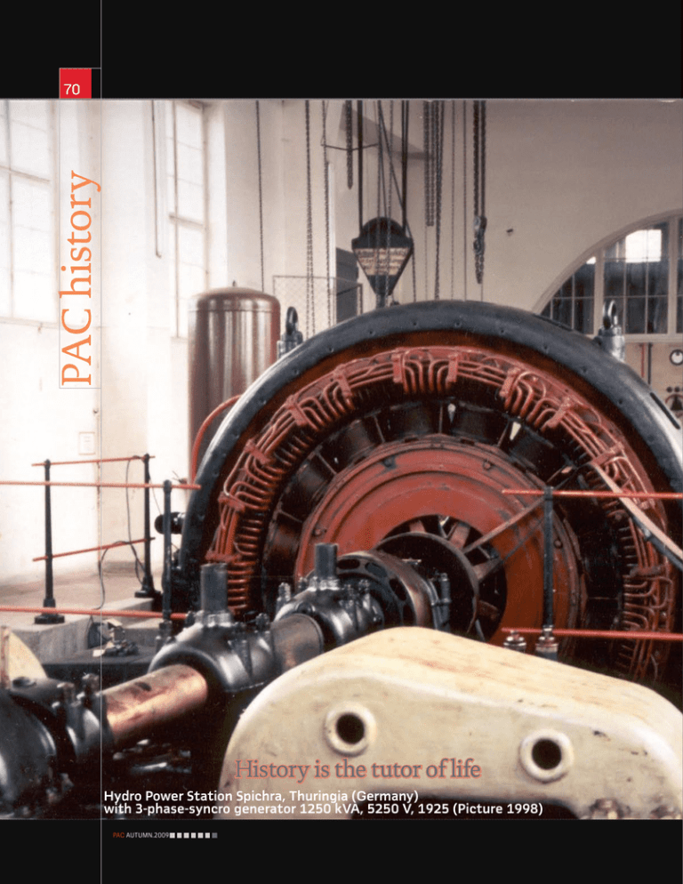
PAC history 70 History is the tutor of life Hydro Power Station Spichra, Thuringia (Germany) with 3-phase-syncro generator 1250 kVA, 5250 V, 1925 (Picture 1998) PAC.AUTUMN.2009 by Walter Schossig, Germany Protection 71 History Limiting the Damages Biography Generator Protection Stator Ground-Fault Protection of Generators The first protection devices for overload, short-circuit, overand undervoltage, as well as differential and reverse-power protection were described in the last issues of PAC World. Another possibility to limit damages was made available by the introduction of ground-fault protection. The magnitude of the expected fault current depends on the type of star point grounding of the generator. If the neutral is earthed, fault currents are as huge as short-circuit currents. In case of isolated neutral point, only earth-fault currents or even residual currents will occur. The magnitude also depends on the location of the fault in the winding. One of the first forms of supervision of earth faults in DC power stations was realized with bulbs (Figure 3). If the red light turned off, an earth-fault or an interruption in the connection to the plus-pole was the reason. If the blue light turned off - the minus pole was involved. If both lamps were off - a short circuit or an interruption occurred. If the isolation of a winding became faulty, an arc to the earthed ground of the machine occurred. The overcurrent circuit breaker tripped at a value between 1.5 and 2-times of the nominal current of the machine. Due to that, an arc could develop at huge currents without a trip of the main circuit breaker. Very often due to strong air flow caused by the machine the arc remained for a long time and the breaker tripped too late. Emil Neumann proposed in his patent DRP 314415 in 1919 to isolate the machine against earth and to realize the earthing with a certain connection, (Figure 4) a resistance, a reactor or a current transformer. In case of a failure in the isolation in the isolated machine a current flows between the winding and the cabinet, causing a voltage on the clamp. Even a small problem in the isolation caused a small current and a small voltage that could be used for indications or alarms. In case of a further increase of the current, the generator would be switched off. In case of a separately excited machine, the patent describes the usage of a resistance in the excitation. Different approaches have been developed in Europe and the United States for neutral grounding in AC grids. Solid or low-resistance grounding was not that popular in Europe due to the large earth-fault currents and even in case of fast earth fault protection the stator lamination could melt (“core-burning”). Isolated or high resistance grounding was the preferred choice. Dr. Piloty, AEG, described in 1929 different approaches regarding neutral earthing and proposed PAC.AUTUMN.2009 Walter Schossig (VDE) was born in Arnsdorf (now Czech Republic) in 1941. He studied electrical engineering in Zittau (Germany), and joined a utility in the former Eastern Germany. After the German reunion the utility was renamed as TEAG, now E.ON Thueringer Energie AG in Erfurt. There he received his Masters degree and worked as a protection engineer until his retirement. He was a member of many study groups and associations. He is an active member of the working group “Medium Voltage Relaying” at the German VDE. He is the author of several papers, guidelines and the book “Netzschutztechnik [Power System Protection]”. He works on a chronicle about the history of electricity supply, with emphasis on protection and control. PAC history 72 1 Frame-leakage protection RW7e (Siemens, 1938) 2 Annular Core Current Transformers 4 recommendations for the estimation of grounding resistances. Housing earth fault protection, Neumann, He mentioned the advantage of voltage dependent resistances 1919 at this time. Wattmetric earth fault protection of generators was difficult, especially in the case of small earth fault currents, and if more than 30 % of the winding should be protected. Thus C B solutions had been needed to increase the fault current to A allow a measurement with full neutral-displacement voltage, but avoiding core-burning. The common schemes are shown L in Figure 5. SIEMENS preferred scheme a) BBC contactors as b). These R contactors switched on a bigger resistance depending on the neutral voltage. In 1924 Walter Bütow, AEG, proposed to increase the N M G sensitivity of the earth fault protection in the neutral of the generator with voltage and current depending resistances (“Iron –Resistance”, Figure 6, DRP 458137). It is also D known as „Bütow-Protection“. Figure 7 shows a generator protection board with the resistances on top. The number of used lamps was such that for the selected zone of protection e 90% of the earth-fault currents had been less than 5 A to avoid core-burning. The self-supervision was realized with a built-in 15). The generators were mounted on concrete fundaments pushbutton (Figure 7 below lamps). Pressing the button with big earth-contact resistance often occurring. They were caused a flash on of all lamps. Another possibility had been connected with the high-voltage earth (protective earthing) carbon-pile regulators, making possible a characteristic such and in this way with the cable jackets of the grid. as c). This earth connection had been equipped with an Courtin, AEG, proposes a realization of generator stator wattmetric relay in an inductive parallel connection. ground-fault protection with iron ribbon-core resistances If the earth-fault current of the grid connected was not (Figure 9). The generator protection developed in the early sufficient to trip the frame-leakage protection, a ground-fault stages was sensitive and stable, nevertheless false tripping reactor was connected to the busbar. The secondary sometimes occurred. They spoke about a “general disturbance delta-winding was under load with a resistance. The reactor in the grid” and started huge investigations and developments and the coil were required only once for all generators in the 1920s. connected to the same busbar (Figure 8). One proposal for a cheap and selective protection for small To realize a frame-leakage protection with constant machines was made by H.Seel in Leipzig in 1962 (Figure relay-voltage and linear-depending torsional relays Siemens 3 Earth fault supervision scheme (USSR, 1937) 5 Limitation of earth fault currents iE iE U0 U0 iE U0 U2 G U1 iE a) b) iE c) iE G - Generator PAC.AUTUMN.2009 - Lamps U0 100% a - Constant Resistance: U0 100% b - Tapped U0 100% c - Ferrum-Hydrogen (FeH) 73 Wattmetric relays were introduced in the 1940s for protection of generators. developed a “selector relay scheme” for star connected windings (Figure 13). In case of a failure, the frame-leakage relay received a constant alternating current instead of the varying zero sequence voltage. The selector d delivered to the relays a voltage, which was dependent on the faulty phase over the transformer i. To increase the sensitivity, Siemens replaced the permanent magnetic field of a moving coil with a stronger electrically produced DC-field. Wattmetric relays with current and voltage paths were used (Figure 1). Direction-of-power relays with error current stabilization were used in the Soviet Union in 1933-1945. The first realizations of these relays protected 92, 87 or 74 % of the length of the stator winding (values valid for generators with a nominal voltage of 10.5, 6.3 and 3.15 kV. The sensitivity was selected with the precondition that the end of the protection area near the generator neutral was 500 Volts. This value was not sufficient to supply a lightning arc. The zero sequence currents were created in a Holmgreen – a scheme that caused high error currents depending on the magnetic characteristic of the measurement transformer. That is why bushing-type current transformers for cables with a clamp-on core were developed in the USSR in 1937 (Figure 2). After the Second World War, the Soviets developed and used bushing-type current transformers with auxiliary magnetization (Figure 12). Such a transformer consists of identical iron cores. Due to the long rectangular shape of the core it was possible to pull several three-conductor 7 Generator protection Bütow, AEG, approximately 1940 Lamps were used to determine the selected zone of protection. 8 Stabilized differential & frame-leakage protection for generator busbar operation Siemens 9 Stator ground-fault protection Courtin, AEG, 1934 Realization Scheme 6 Wattmetric earth-fault detection using FeH-Resistances and a Holmgreenscheme (1930) TR EW G S NSp E R N NST NT ZT k 28426 ER - Earth Fault Relays SpR - Voltage Relays EW - Iron Ribbon-Core Resistance NSp - Neutral Voltage Transformer NT - Neutral Transformer Resistance NST - Neutral Current Transformer PAC.AUTUMN.2009 PAC history 74 12 Bushing-type current transformers with auxiliary magnetization, USSR 10 Directional earth-fault relay R1W3 (Siemens, approximately 1950) cables through one core. This could be done in a row or as a chessboard (see Figure 12). The auxiliary winding consists of two sections, supplied by an independent AC-source (as a generator voltage transformer). Since the two sections were connected in series, (the excited magnetic fluxes are opposing), this setup compensates the electromagnetic forces. Using ferromagnetic alloys with big magnetic permanence (as Permalloy) further increased the sensitivity and decreased 11 Stator ground-fault relay 13 Selector relay scheme, Siemens, approximately 1930 Bushing-type current transformers allowed the development of new protection schemes. error currents. Using these bushing-type current transformers allows operating stator-ground fault protection with currents up to 5 A. Such small currents required sensitive current relays with low consumption of auxiliaries. In 1948/49 engineers in the Soviet Union started a series of tests with high sensitive current earth fault-relays. They were developed for generators with cable connections (Figure 14). The toroidal-core current transformers are made of Permalloy. One transformer was used for one cable. In case of several cables, the transformers were connected in parallel. To connect them in series was also discussed. However, in that case the disadvantage was large inductions in the core in case of unsymmetrical primary values. The current relay itself was connected via an amplifier to the current transformer, so relays with normal friction loss could be used. The sensitivity alternates between 2.5 and 5 for ten to twelve cables. The whole developments in the USSR were driven by Prof. Dr. G. I. Atabekov (Moscow). Siemens used high sensitive moving-coils directional relays R1W3 in the 1950s (Figure 10). They were connected to cable-type current transformers 60/1 A and were supplied with the line-to-line voltage and the displacement voltage. Utilizing cable-type transformers was no longer possible with large generators and infeeds with busbars. Stabilization and adjustment of CTs allowed usage of Holmgreen schemes. This scheme consists of three current transformers with a ratio of 100. The secondary sides are connected in parallel. The precondition was an adjustment of the three transformers 14 Stator ground-fault protection, USSR, 1949 Stator Ground-Fault Protection with Toroidal-Core Current Transformers and Amplifieres (RERZG, EAW, 1959) PAC.AUTUMN.2009 75 with equal characteristics to avoid false tripping of the earth-fault protection. An auxiliary resistance was connected to increase the sensitivity of the wattmetric earth fault protection during startup of the generator. Using wattmetric stator ground-fault protection required the vector of the displacement voltage. In case of sustained ground fault and during transients, very often false tripping occurred. Investigations of these false trippings were very difficult, because the behavior of the relay during stationary conditions was perfectly fine. Another disadvantage of the wattmetric relays was the decreasing torque with the square of earth-current and -voltage. To gain linear dependencies special methods were developed, such as voltage-stability, selection of voltage or selecting a single phase of an artificial three-phase system. A pure current relay was much simpler. If this relay would use the fault current from a core-balanced CT without consideration of voltage, it would false trip. Bruno Westphal, Siemens, used a simple compensation scheme in 1950. A small interposing transformer was used in the neutral return system. The secondary side supplies a rectifier connected with the genuine earth-fault relays. A zero sequence current caused a trip, while the compensation current caused a torque in blocking direction. In case of a generator fault the compensation was weak (Figure 18). The Swiss “Maschinenfabrik Oerlikon” patented a scheme for sum current transformers with common magnet core. This scheme used the principle of pre-magnetization to increase sensitivity (Figure 17). The core consists of two parts. The winding 9 is excited in such a manner that the fluxes in the main winding are compensated. The current source for excitation of winding 9 is the tertiary winding of the three-phase reactor 6. In this reactor there is only current in case of an earth-fault. An advantage of this scheme was that in case of a fault the sensitivity is increased due to an improvement in the magnetic characteristic of the CT. The scheme is stable in case of no earth faults. EAW produced wattmetric directional earth-fault relays RERZG in 1959 (Figure 11). To minimize the neutral point transformer f3 (Figure 21) in case of an earth-fault detected by (e2), the FeH-resistance is disconnected via a relay’s c1 after 2 seconds. The fault inside the generator is cleared by e1 with a delay of 0.5 seconds. The buttons b1 … bn were used for testing of the FeH lamps (Figure 16). Westinghouse presented the directional negative sequence relay for ground protection CRG in 1974. Figure 20 shows the discriminating element. Blackburn,J.L. proposed another Westinghouse solution in 1977 (Figure 19). The CWC as presented in 1973 is shown in Figure 22. A special scheme to connect stator ground fault relay presented by BBC shows Figure 25. To receive the zero sequence current the transformer T6 is equipped with additional secondary windings 3p-3q in every phase on the short-circuited core 3k-3l. The reference voltage is the phase-phase voltage of the busbar voltage transformers. 15 Stator ground-fault protection, Seel, 1962 16 Baretter Lamps FeH Baretter lamps change their resistance as a function of their heating. 17 Stator ground 18 False current stabilization, fault Westphal (Oerlikon, 1953) (Siemens, approximately 1950) + PAC.AUTUMN.2009 PAC history 76 21 Scheme RERZG and REG5, EAW, 1959 a1 23 SEG, AEG, 1989 x RERZG f1 e1 G 3~ f2 e2 f5 g1 f4 c1 f3 f4 and f5 8/0,15 A U > REG5 L1 N b1 5x b2 bn 4x10x 5x FeH e2 Earth fault detection b1...bn buttons for testing FeH lamps 19 Blackburn' s proposal (Westinghouse, 1977) A generator ground stator protection with third harmonic was developed by Westinghouse in 1981 (Voltage Comparator, type DGSH, Figure 24). The CV-8 (Figure 26) filtered the 3rd harmonics and reached a sensitivity of 8%. The stator ground-fault relays SEG presented by AEG in 1993 used the earth-fault current or the unbalanced residual current for the estimation of the direction of earth-fault (Figure 23). The adaptation of the current was utilized by the coupling measuring W01 or WE115. W01 / WE115 Coupling measuring the current 24 Generator ground stator protection DGSH, Westinghouse, 1981 Generator ground stator protection with third harmonic 25 Relays DPX113, BBC (Scheme for Connection of Stator Ground-Fault, 1978) Stator ground-fault protection for generators with unit-transformers and other apparatus will be discussed in a later article. walter.schossig@pacw.org www.walter-schossig.de 20 Directional negative sequence relay for ground protection 22 External schematic of the ground differ- 26 Scheme CV-8, ential protection CWC, Westinghouse, 1973 (CRG, Westinghouse, 1974) PAC.AUTUMN.2009 Westinghouse, 1987
