Kinematic Analysis of the Sewing Mechanisms of an Overedge Machine Ryszard Przytulski,
advertisement

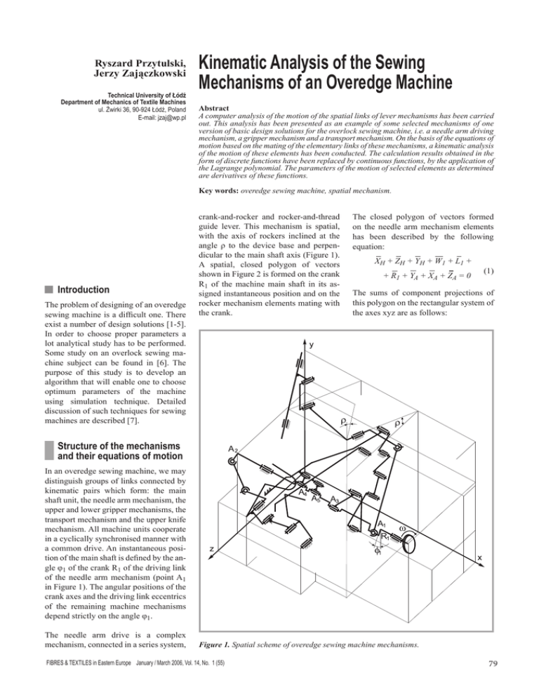
Ryszard Przytulski, Jerzy Zajączkowski Technical University of Łódź Department of Mechanics of Textile Machines ul. Żwirki 36, 90-924 Łódź, Poland E-mail: jzaj@wp.pl Kinematic Analysis of the Sewing Mechanisms of an Overedge Machine Abstract A computer analysis of the motion of the spatial links of lever mechanisms has been carried out. This analysis has been presented as an example of some selected mechanisms of one version of basic design solutions for the overlock sewing machine, i.e. a needle arm driving mechanism, a gripper mechanism and a transport mechanism. On the basis of the equations of motion based on the mating of the elementary links of these mechanisms, a kinematic analysis of the motion of these elements has been conducted. The calculation results obtained in the form of discrete functions have been replaced by continuous functions, by the application of the Lagrange polynomial. The parameters of the motion of selected elements as determined are derivatives of these functions. Key words: overedge sewing machine, spatial mechanism. n Introduction The problem of designing of an overedge sewing machine is a difficult one. There exist a number of design solutions [1-5]. In order to choose proper parameters a lot analytical study has to be performed. Some study on an overlock sewing machine subject can be found in [6]. The purpose of this study is to develop an algorithm that will enable one to choose optimum parameters of the machine using simulation technique. Detailed discussion of such techniques for sewing machines are described [7]. crank-and-rocker and rocker-and-thread guide lever. This mechanism is spatial, with the axis of rockers inclined at the angle ρ to the device base and perpendicular to the main shaft axis (Figure 1). A spatial, closed polygon of vectors shown in Figure 2 is formed on the crank R1 of the machine main shaft in its assigned instantaneous position and on the rocker mechanism elements mating with the crank. The closed polygon of vectors formed on the needle arm mechanism elements has been described by the following equation: XH + ZH + YH + W1 + L1 + + R1 + YA + XA + ZA = 0 (1) The sums of component projections of this polygon on the rectangular system of the axes xyz are as follows: n Structure of the mechanisms and their equations of motion In an overedge sewing machine, we may distinguish groups of links connected by kinematic pairs which form: the main shaft unit, the needle arm mechanism, the upper and lower gripper mechanisms, the transport mechanism and the upper knife mechanism. All machine units cooperate in a cyclically synchronised manner with a common drive. An instantaneous position of the main shaft is defined by the angle φ1 of the crank R1 of the driving link of the needle arm mechanism (point A1 in Figure 1). The angular positions of the crank axes and the driving link eccentrics of the remaining machine mechanisms depend strictly on the angle φ1. The needle arm drive is a complex mechanism, connected in a series system, Figure 1. Spatial scheme of overedge sewing machine mechanisms. FIBRES & TEXTILES in Eastern Europe January / March 2006, Vol. 14, No. 1 (55) 79 XH + W1 cosα1 + L1 cosηX + - XA1 = 0, YH - W1 sinα1 cosρ - L1 cosηY + + R1cosφ1 - YA = 0, (1a) ZH + W1 sinα1 sinρ + L1 cosηZ + - R1 sinφ1 - ZA = 0. In the system of Equations 1a and 1b, the desired parameters of the instantaneous position in space of the link L1 are the angles ηx, ηy, ηz and the inclination angle α1 of the rocker W1 to the axis x. The additional equation that makes it possible to calculate the above-mentioned angles is as follows: cos2ηx + cos2ηy + cos2ηz -1 = 0 (1b) The rocker W2, displaced in phase with respect to the first rocker, is mounted on the rocker W1 axis inclined at the angle θ to the machine base. The rocker W2 with the link L2 and the needle arm constitute a flat mechanism in the system of the axes ux (Figure 2). The geometrical sum of vectors formed on these elements has been written as: XH + XG + Uig + L2 + W2 = 0 (2) The sums of component projections of this polygon are as follows: XH - XG - L2 sinβ2 - W2 cosα2 = 0 (2a) - Uig + L2 cosβ2 - W2 sinα2 = 0 Figure 2. Systems of vectors formed on needle arm mechanism elements. On the basis of Equations 2a, the angle β2 and the displacement of the needle arm Uig have been determined as a function of the assigned angle φ1 of the machine main shaft rotation. In overlock overedge sewing machines, a lower gripper moves below the fabric, and the mating upper gripper comes above the fabric, to form an elementary interlacing. The crank R2 on the main shaft puts the gripper mechanisms into motion. To develop a kinematic analysis of the upper gripper element motion, a spatial polygon of vectors has been constructed (Figure 3). The closed polygon of vectors related to the rocker W3 is as follows: YA + ZA + R2 + L3 + W3 + + YF + XF + ZF = 0 (3) The sums of component projections of these vectors on the axes take the form: L3 cosγx + W3 cosα3 - XF = 0 YA - R2 cosφ2 - L3 cosγy + + W3 sinα3 - YF = 0 ZA - R2 sinφ2 - L3 cosγz - ZF = 0 80 (3a) Figure 3. System of vectors of the instantaneous position of gripper mechanism elements. FIBRES & TEXTILES in Eastern Europe January / March 2006, Vol. 14, No. 1 (55) elements has been described by three flat closed polygons of vectors formed on the geometrical relationships of the relative positions of its links (Figure 4). The polygon formed on the basis of the first rocker mechanism is as follows: ZA + R3 + L5 + W6 + YB + + ZB + YA = 0 (5) and the sums of projections of its components are: YA - R3 cosφ3 - L5 sinβ5 + - W6 cosα6 - YB = 0 ZA + R3 sinφ3 - L5 cosβ5 + + W5 sinα6 - ZB = 0 (5a) The second polygon of vectors is formed by: W8 + ZC + YC + ZB + YB + + W7 + L6 = 0 (6) and the system of equations obtained from the sum of projections of its components is: YB - W7 cosα7 - L6 cosβ6 + - W8 sinα8 - YC = 0 ZB - W7 sinα7 + L6 sinβ6 + - W8 cosα8 - ZC = 0 Figure 4. Systems of vectors that describe the motion of transport mechanism elements. The desired parameters of the instantaneous position in space of the link L3 are the angles γx, γy, γz and the inclination angle α3 of the rocker W3. The additional equation that allows the calculation of the above-mentioned angles is as follows: cos2γx + cos2γy + cos2γz -1 = 0 (3b) The rockers W3 and W4 constitute one rigid link, and are displaced in phase with respect to each other. The rocker W4 drives the rocker W5 of the lower gripper through the link L4. This system of links constitutes a flat mechanism (Figure 3). The geometrical sum of vectors formed on the lower gripper elements is written as: W4 + L4 + W5 + YK + XK + + XF + YF = 0 (4) The sums of projections of component vectors of the polygon formed on these links are as follows: XF - W4 cosα4 - L4 cosβ4 + + W5 sinα5 - XK = 0 YF + W4 sinα4 - L4 sinβ4 + + W5 cosα5 - YK = 0 On the basis of the system of Equations 4a, the angle β4 of the link position and the angle α5 of the rocker position of the lower gripper have been determined as a function of the assigned angle φ1 of the machine main shaft rotation. In the presented machine design solution, the trajectory of the transport mechanism toothed bar is formed by a summation of the motion of both the link systems from the two driving links of the main shaft. The main part of the first mechanism consists of two double-arm rockers connected in series. The displacement of the transporting bar upwards and downwards is forced by the motion of the link of the second drive system. The mating of all the transport system mechanism FIBRES & TEXTILES in Eastern Europe January / March 2006, Vol. 14, No. 1 (55) The third polygon related directly to the toothed bar link takes the form: ZA + ZC + YC + W9 + L7 + (4a) (6a) + L8 + R4 + YA = 0 (7) whose sum of component projections is represented by the following equations: YA + R4 cosφ4 + L8 cosβ8 + - L7 sinβ7 - W9 cosα9 - YC = 0 (7a) ZA - R4 sinφ4 - L8 sinβ8 + - L7 cosβ7 + W9 sinα9 - ZC = 0 The angles β5, α6, β6, α8 and β7, β8 of the instantaneous position of rockers and links as a function of the angle φ1 of the machine main shaft rotation have been determined from the systems of Equations 5a, 6a and 7a. The coordinates yT, zT of the transporting bar end point trajectory have been determined from the relationship: YT = YC + W9 cosα9 + + (L7 + LT)sinβ7 ZT = ZC + W9 sinα9 + (8) + (L7 + LT)cosβ7 81 The computations for all the mechanism links in the machine under consideration have been performed. The results of the calculations for some selected machine elements, on the assumption of a unit angular velocity of the main shaft, are shown in Figures 5, 6 and 7. This program for calculating the parameters of spatial mechanism kinematics, as formed on the mechanisms of the overedge sewing machine, is a basic tool in the computer analysis of the dynamics of these mechanisms which are currently being developed. n Conclusions 1. The algorithm presented in this paper together with a computer program developed at the Department of Mechanics of textile Machines were used enables finding appropriate dimensions of machine elements of an overedge sewing machine. 2. This study proved that mathematical modelling is a very efficient tool for designing of modern high speed overedge sewing machines. Figure 5. Position, velocity and acceleration of the needle arm along the axis u as a function of the rotation angle φ1 of the main shaft crank R1. Figure 6. Displacement, velocity and angular acceleration of: a) the upper gripper; b) the lower gripper as a function of the rotation angle φ1 of the main shaft crank R1. Figure 7. Trajectory of the transporting bar end point in the plane yz. Overedge sewing machines are equipped with a knife mechanism whose task is to trim fabric edges to ease the performance of the technological process. The upper knife drive, being a simple crank-androcker mechanism, has not been considered in the present paper. Data for calculations and the result of the computational analysis The measurements of the parameters of the link geometry and their mutual 82 spatial positions have been carried out on a physical model of the three-tread overedge machine GN1-1 (made in China). The set of necessary quantities to perform the motion calculations for only one mechanism of the needle arm of this machine is as follows: R1 = 0.0075; L1 = 0.067; L2 = 0.016; W1 = 0.0285; W2 = 0.0415; XA1 = 0.138; YA = 0.073; ZA = 0.079; XH = 0.111; YH = 0.1345; YH1 = 0.1495; ZH = 0.0535; ZH1 = 0.0885; XG = 0.070; Xig = 0.0575; ν12 = π; ρ = 23π /180. References 1. Hsien Chang Tseng: Sewing machine control mechanism. US Patent 5,704,303 (1998). 2. Pozzi G. Sanvito R.: Overedge sewing machine including an upper looper with a hooked member. US Patent 5,465,675 (1995). 3. Gosche M. J.: Overedge stitch sewing device. US Patent 5,465,674 (1995). 4. Baba Y., Satoma S.: Overlock sewing machine. US Patent 5,255,622 (1993). 5. Holl H., Meier G.: Overcast sewing machine for forming a multiple-tread overcast seam. US Patent 5,269,240 (1993). 6. Owczarek A.: ‘Computer models of selected mechanisms used in sewing machines (in Polish)’, M. Sc. thesis, Technical University of Łódź, 2002. 7. Zajączkowski J.: Komputerowe modelowanie maszyn włókienniczych. PAN, (2004). Received 23.03.2005 Reviewed 18.11.2005 FIBRES & TEXTILES in Eastern Europe January / March 2006, Vol. 14, No. 1 (55)


