Circular BarGraphs BG Series AC Power
advertisement
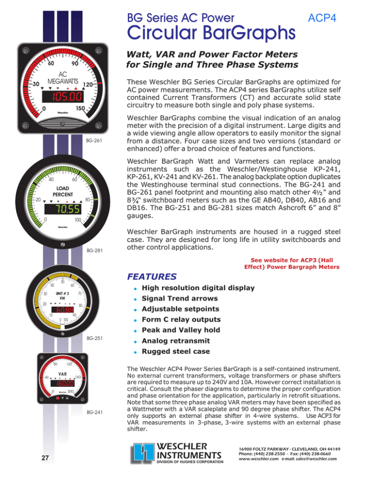
BG Series AC Power Circular BarGraphs 60 Watt, VAR and Power Factor Meters for Single and Three Phase Systems 90 AC MEGAWATTS 120 30 150 0 BG-261 40 60 LOAD PERCENT 20 0 ACP4 80 100 BG-281 These Weschler BG Series Circular BarGraphs are optimized for AC power measurements. The ACP4 series BarGraphs utilize self contained Current Transformers (CT) and accurate solid state circuitry to measure both single and poly phase systems. Weschler BarGraphs combine the visual indication of an analog meter with the precision of a digital instrument. Large digits and a wide viewing angle allow operators to easily monitor the signal from a distance. Four case sizes and two versions (standard or enhanced) offer a broad choice of features and functions. Weschler BarGraph Watt and Varmeters can replace analog instruments such as the Weschler/Westinghouse KP-241, KP-261, KV-241 and KV-261. The analog backplate option duplicates the Westinghouse terminal stud connections. The BG-241 and BG-261 panel footprint and mounting also match other 4½ " and 8 ¾" switchboard meters such as the GE AB40, DB40, AB16 and DB16. The BG-251 and BG-281 sizes match Ashcroft 6” and 8” gauges. Weschler BarGraph instruments are housed in a rugged steel case. They are designed for long life in utility switchboards and other control applications. See website for ACP3 (Hall Effect) Power Bargraph Meters FEATURES 50 40 60 UNIT # 3 KW 30 ! High resolution digital display 70 20 ! Signal Trend arrows 80 ! Adjustable setpoints 90 10 ! Form C relay outputs 0 100 ! Peak and Valley hold BG-251 ! Analog retransmit ! Rugged steel case 80 120 VAR 40 0 Weschler 160 200 BG-241 27 The Weschler ACP4 Power Series BarGraph is a self-contained instrument. No external current transformers, voltage transformers or phase shifters are required to measure up to 240V and 10A. However correct installation is critical. Consult the phaser diagrams to determine the proper configuration and phase orientation for the application, particularly in retrofit situations. Note that some three phase analog VAR meters may have been specified as a Wattmeter with a VAR scaleplate and 90 degree phase shifter. The ACP4 only supports an external phase shifter in 4-wire systems. Use ACP3 for VAR measurements in 3-phase, 3-wire systems with an external phase shifter. WESCHLER INSTRUMENTS DIVISION OF HUGHES CORPORATION 16900 FOLTZ PARKWAY - CLEVELAND, OH 44149 Phone: (440) 238-2550 - Fax: (440) 238-0660 www.weschler.com e-mail: sales@weschler.com FEATURES Wattmeters and Varmeters Measurement Range Potential Range Self-Contained Current Maximum Numeric Display Characters Numeric Display Color Bar Color Bar Segments Bar Resolution Display Brightness Alarm Hysteresis Relays Relay Latching Mode Relay Fail-safe Mode HI - LO Alarms Analog Retransmit Standard ± 19999 120, 240 V rms 10 A rms 4½ Digit Red Red 101 1% Fixed 0.5, 1 & 2% FS 2 or 4 Form C N/A N/A 2 HI, 2 LO 256 Step Resolution Enhanced -9999 to 50000 (Neg Autoscale) 120, 240 V rms 10 A rms 4¾ Digit Red, Green or Amber Red, Green or Amber 101 1% Two Level Programmable 0.0-10.0% FS 2 or 4 Form C Yes N/A Individually Programmable 65000 Step Resolution SPECIFICATIONS Inputs Potential (Voltage) Nominal Maximum Continuous Momentary Overload Input Impedance Current Nominal Maximum Continuous Momentary Overload Input Impedance Frequency Response Time Uncertainty Display (W or VAr) Setpoints Temperature Coefficient Standard Enhanced Bar Display Scale Length BG-241 BG-261/281 BG-251 Digital Display Resolution Standard Enhanced Height BG-241 BG-261/281 BG-251 Communications RS-232 120, 240 Vac 150, 300 Vac 175, 325 Vac 1MW 10 A 12.5 A 100 A for 500 ms Internal CT, 0.1W 50/60 or 400 Hz 1 sec. Enhanced Contact Ratings Contact Protection Hysteresis Analog Retransmit Standard ± 0.5% Full Scale, ± 1 count ± 0.1% Full Scale, ± 1 count Enhanced ± 1.3 ppm / °C ± 0.5 ppm / °C Environment Operating Temperature Humidity 0 285 0 270 0 0 270 /345 0.005% 0.002% 0.4" (10.16 mm) 0.8" (20.32 mm) 0.56" (14.22 mm) Protocol 9600 baud, 1 start bit, 1 stop bit, no parity, no flow control Half duplex, 9600 baud, 1 start bit, 1 stop bit, no parity, no flow control Party Line AC Sensing Method Electronic RS-485 Setpoint Relays Quantity Contact Arrangement Type Standard Storage Temperature 2 or 4 SPDT (Form C) 2 HI (ascending trip) and 2 LO (descending trip) All programmable HI or LO 5A, 120/240 Vac or 30 Vdc resistive 1/14 HP 120/240 Vac inductive MOV clamp Selectable for all setpoints collectively 256 step resolution, voltage source 0-1, 4-20, 10-50 ma; 0-5, 1-5 V 65000 step resolution, current source 0-24 ma, 0-10 V programmable -20 to 60°C (Standard) -20 to 50°C (Enhanced) 0- 95% non-condensing. Condensation allowed with conformal coating option. -40 to 85°C Meter Power Nominal Tolerance Current (Maximum) Standard Enhanced 12 V DC 10-15 V 225 ma 825 ma 24 V DC 18-36 V 125 ma 420 ma 28 V DC 18-36 V 100 ma 350 ma 48 V DC 36-72 V 65 ma 210 ma 250 V DC ± 10% 12 ma 25 ma 120 V AC ± 10% (50/60 Hz) 2.5 VA 12.5 VA 240 V AC ± 10% (50/60 Hz) 1.3 VA 12.3 VA 110-250V DC / 85-264V AC 6 VA (3 W) 13 VA (8W) Fuse Plug-in, rear panel accessible Connections BG Backplate Analog Backplate #6 screw terminals for AC signals; Phoenix plug in connectors for Relays, Analog Retransmit & Communications (mating connector supplied) #10-32 studs for AC signals; Relays, Analog Retransmit and Communications not available 28 ORDERING GUIDE PART NUMBER TYPE: 4 = 6 = 8 = 3 = BG-241 BG-261 BG-281 BG-251 Specify scale markings and legend when ordering DIGIT COLOR**: B = Enhanced Red X = Red (not available on BG251) G = Enhance Green A = Enhanced Amber M = Red with Multi-color bar * S = Special *Enhanced only 4½" Square BarGraph 8½" Square BarGraph 8" Circle BarGraph 6" Circle BarGraph BAR ZERO POINT: B = Zero at Bottom H = Zero at 50% mid scale F = Zero at F.S. S = Special /off scale zero DISPLAY: 4 = 4½ digit Standard E = 4¾ digit Enhanced Y B K A X = = = = = Spraytight Face Analog Backplate Conformal Coating Custom Artwork NA T X = = Trend Indicator NA P X = = Peak/Valley Hold NA COMMUNICATION: A = RS232 C = RS485 Bi-directional X = None SETPOINTS: N = Hi/Lo H = Hi/Hi-Hi L = Lo/Lo-Lo 4 = Hi-Hi/Hi/Lo/Lo-Lo B = 2 relays, programmable Hi or Lo * D = 4 relays, programmable Hi or Lo * X = None S = Special order *Enhanced only RETRANSMIT: A = 4-20mA DC into 250W B = 0-1mA DC into 1000W C = 1-5V DC D = 0-1V DC F = 4-20mA DC, 700 W max. (isolated) G = 0-1mA (isolated) T = 0-10V across 500W (isolated) * K = 0-1V across 50W (isolated) * M = 1 -5V across 250W (isolated) * X = None *Enhanced only. Isolated requires AC power SETPOINT HYSTERESIS: 1 = 1% of F.S. 2 = 2% of F.S. 5 = 0.5% of F.S. X = Not required S = Special. P = Programmable 0-10% or Latching (Enhanced only) POWER: 1 = 120V AC 50/60Hz 2 = 240V AC 50/60Hz 4 = 12V DC * 6 = 250V DC 7 = 24V DC 8 = 28V DC 9 = 48V DC U = 110-250V DC / 85-264V AC, 50-440Hz INPUT TYPE: L = Watts single phase H = Watts three phase V = VARs single phase Z = VARs three phase Y = VARs three phase for external phase shifter (4-wire only) G = Power factor (display 1.00 max, specify lag on right or left) *Max ambient 45°C INPUT LEVEL: 12 = Single phase two wire 13 = Single phase three wire 33 = Three phase three wire 34 = Three phase four wire 3E = Three phase four wire Specify: CT ratio _____________ Full scale Watts value ___________ PT ratio _____________ External phase shifter ___________ System Delta or WYE 1 element 2 element 2 element 2½ element 3 element **bar color matches digit color unless specified on order EXAMPLE: 4 B 4 N 1 H 3 3 1 F A P T Y X (4) BG-241, (B) zero at bottom, (4) 4-1/2 digit Standard display, (N) Hi/Lo setpoint, (1) 1% of F.S. setpoint hysteresis, (H) Watts, poly phase, (33) Three phase three wire, (1)120 VAC 50/60 Hz power, (F) 4-20 mADC isolated retransmit, (A) RS232 communication, (P) peak/valley hold, (T) trend indicator, (Y) spray tight face, (X) red LED color Options and features vary by model. Contact factory for details and latest specifications. 29 WESCHLER INSTRUMENTS DIVISION OF HUGHES CORPORATION 16900 FOLTZ PARKWAY - CLEVELAND, OH 44149 Phone: (440) 238-2550 - Fax: (440) 238-0660 www.weschler.com e-mail: sales@weschler.com DIMENSIONS BG-261 BG-241 A 4.421" 112.3 mm 8.75” 222.25 mm 0.69” 17.5 mm 1.02" 25.9 mm A 1/4-28 x 5/8" studs 4.421" 112.3 mm 8.75” 222.25 mm 3.96” 100.6mm FRONT VIEW FRONT VIEW SIDE VIEW A= 5.15" (130.8mm). Add 0.6" (15mm) for screw terminals or 0.85" (22mm) for studs on analog backplate BG-251 / 281 BG-251=7.562" 192.1 mm BG-281=10.062” 255.6 mm SIDE VIEW BG-251=5.1-6.55" DIA. 130-167 mm BG-281=5.1-8.91" DIA. 130-226 mm 1.05" 26.7 mm A 3.96” 100.6 mm 1.687" 42.850 mm 1.687" 42.850 mm 0.315" DIA. (X4) 8.001 mm 1200 1200 1.687" 42.850 mm 3.96" 100.6 mm 4.0" DIA. 101.6 mm 0.312" DIA. TYP. 7.925 mm FRONT VIEW ALTERNATE PANEL CUTOUT FOR BG-251 / 281 SIDE VIEW 1.687" 42.850 mm BG-251=6.88" DIA. 174.75 mm BG-281=9.508" DIA. 241.5 mm PANEL CUTOUT Mounting Torque 65-70 inch-pounds max. TERMINAL CONNECTIONS C B + - 1 RELAYS ReTx A N C B A BarGraph Power 123 6 5 4 3 2 1 COMM ReTx 7 8 9 10 11 12 7 8 9 10 11 12 LOAD 1f 2Wire Wattmeter BarGraph Power - 2 C B 123 COMM 6 5 4 3 2 1 Fuse 1 1 RELAYS 12 Fuse LOAD 3f 4Wire Varmeter (3 element) 1 RELAYS 12 COMM 6 5 4 3 2 1 3f 4Wire Wattmeter BarGraph Power ReTx 123 12 Fuse N + 3f 3Wire Wattmeter BarGraph Power - A + B - C 7 8 9 10 11 12 LOAD 3f 3Wire Wattmeter A N C B 3f 4Wire Varmeter with Phase Shifter A (Analog Back) (Analog Back) 1 2 3 4 5 6 + MV-832 ReTx 1 RELAYS 123 12 6 5 4 3 2 1 Fuse COMM 1 2 4 3 7 8 9 10 11 12 5 3 1 2 4 5 + LOAD See Manual for other configurations 8 7 10 + - 6 9 BarGraph Power 6 9 8 7 10 BarGraph Power 10/1/12 LOAD LOAD 30
