EE215, Laboratory 5 Page 1
advertisement

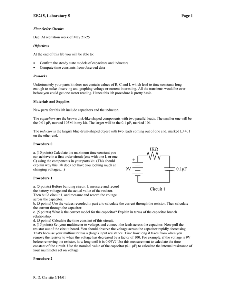
EE215, Laboratory 5 Page 1 First Order Circuits Due: At recitation week of May 21-25 Objectives At the end of this lab you will be able to: Confirm the steady state models of capacitors and inductors Compute time constants from observed data Remarks Unfortunately your parts kit does not contain values of R, C and L which lead to time constants long enough to make observing and graphing voltage or current interesting. All the transients would be over before you could get one meter reading. Hence this lab procedure is pretty basic. Materials and Supplies New parts for this lab include capacitors and the inductor. The capacitors are the brown disk-like shaped components with two parallel leads. The smaller one will be the 0.01 μF, marked 103M in my kit. The larger will be the 0.1 μF, marked 104. The inductor is the largish blue drum-shaped object with two leads coming out of one end, marked LJ 401 on the other end. Procedure 0 a. (10 points) Calculate the maximum time constant you can achieve in a first order circuit (one with one L or one C) using the components in your parts kit. (This should explain why this lab does not have you looking much at changing voltages…) 1KΩ + 9V 0.1μF Procedure 1 a. (5 points) Before building circuit 1, measure and record Circuit 1 the battery voltage and the actual value of the resistor. Then build circuit 1, and measure and record the voltage across the capacitor. b. (5 points) Use the values recorded in part a to calculate the current through the resistor. Then calculate the current through the capacitor. c. (5 points) What is the correct model for the capacitor? Explain in terms of the capacitor branch relationship. d. (5 points) Calculate the time constant of this circuit. e. (15 points) Set your multimeter to voltage, and connect the leads across the capacitor. Now pull the resistor out of the circuit board. You should observe the voltage across the capacitor rapidly decreasing. That's because your multimeter has a (large) input resistance. Time how long it takes from when you remove the resistor to when the voltage has decreased by a factor of 100. For example, if the voltage is 9V before removing the resistor, how long until it is 0.09V? Use this measurement to calculate the time constant of the circuit. Use the nominal value of the capacitor (0.1 μF) to calculate the internal resistance of your multimeter set on voltage. Procedure 2 R. D. Christie 5/14/01 EE215, Laboratory 5 Page 2 a. (5 points) Before building circuit 2, measure and record 1KΩ the battery voltage and the actual value of the resistor. Then build circuit 2, and measure and record the voltage across the inductor. + b. (5 points) Use the values recorded in part a to calculate the current through the inductor. 9V 100 mH c. (5 points) What is the theoretically correct model for the inductor in this circuit? Explain in terms of the branch relationship. d. (10 points) What is a better model for the actual physical inductor in the parts kit. (Hint - measure the resistance of Circuit 2 the physical inductor.) e. (10 points) Calculate the time constant of this circuit using the model in section d and the values from part a. Extra Credit (10 points) Obtain a capacitor that, in combination with resistor(s) from your parts kit, gives a time constant of about 10 sec. You will have to buy it from Radio Shack or other source. I'm not sure if EE stores stocks any. Recall that this is extra credit when you become irritated by this. Design a circuit that sets the initial voltage at about 1V, and, after removing a resistor, lets the final voltage go to about 9V. (The time constant of the pre-removal circuit is not important - it can be quite short.) Start the transient by removing the appropriate resistor. Record voltage across the capacitor. Choose a constant interval between voltage measurements. Plot the series of voltage versus time. Derive the time constant from the graph. Calculate capacitance from your measurements and compare to the nominal capacitor value. (You should use measured values of battery voltage and resistance for the most accurate calculation. You might even need the meter resistance from procedure 1!) Reinsert the resistor and remove the battery, to leave the capacitor in a discharged state (always safer). R. D. Christie 5/14/01


