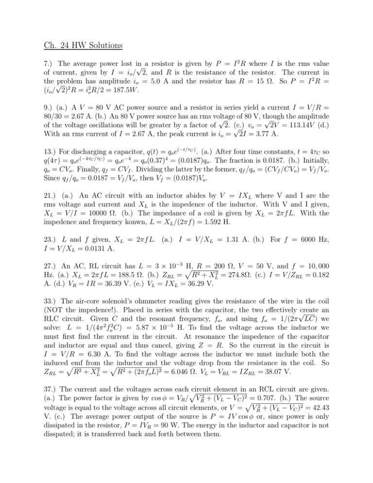
Ch. 24 HW Solutions
advertisement

Ch. 24 HW Solutions 2 7.) The average power lost in √ a resistor is given by P = I R where I is the rms value of current, given by I = io / 2, and R is the resistance of the resistor. The current in the √ problem has amplitude io = 5.0 A and the resistor has R = 15 Ω. So P = I 2 R = (io / 2)2 R = i2o R/2 = 187.5W . 9.) (a.) A V = 80 V AC power source and a resistor in series yield a current I = V /R = 80/30 = 2.67 A. (b.) An 80 V power source has an rms voltage of 80 V, though the amplitude √ √ of the voltage oscillations will be greater by a factor of 2. √ (c.) vo = 2V = 113.14V (d.) With an rms current of I = 2.67 A, the peak current is io = 2I = 3.77 A. 13.) For discharging a capacitor, q(t) = qo e(−t/τC ) . (a.) After four time constants, t = 4τC so q(4τ ) = qo e(−4τC /τC ) = qo e−4 = qo (0.37)4 = (0.0187)qo . The fraction is 0.0187. (b.) Initially, qo = CVo . Finally, qf = CVf . Dividing the latter by the former, qf /qo = (CVf /CVo ) = Vf /Vo . Since qf /qo = 0.0187 = Vf /Vo , then Vf = (0.0187)Vo . 21.) (a.) An AC circuit with an inductor abides by V = IXL where V and I are the rms voltage and current and XL is the impedence of the inductor. With V and I given, XL = V /I = 10000 Ω. (b.) The impedance of a coil is given by XL = 2πf L. With the impedence and frequency konwn, L = XL /(2πf ) = 1.592 H. 23.) L and f given, XL = 2πf L. (a.) I = V /XL = 1.31 A. (b.) For f = 6000 Hz, I = V /XL = 0.0131 A. 27.) An AC, RL circuit has L = 3 × 10⁻³ p H, R = 200 Ω, V = 50 V, and f = 10, 000 Hz. (a.) XL = 2πf L = 188.5 Ω. (b.) ZRL = R2 + XL2 = 274.8Ω. (c.) I = V /ZRL = 0.182 A. (d.) VR = IR = 36.39 V. (e.) VL = IXL = 36.29 V. 33.) The air-core solenoid’s ohmmeter reading gives the resistance of the wire in the coil (NOT the impedence!). Placed in series with the capacitor, the two effectively √ create an RLC circuit. Given C and the resonant frequency, fo , and using fo = 1/(2π LC) we solve: L = 1/(4π 2 fo2 C) = 5.87 × 10⁻⁵ H. To find the voltage across the inductor we must first find the current in the circuit. At resonance the impedence of the capacitor and inductor are equal and thus cancel, giving Z = R. So the current in the circuit is I = V /R = 6.30 A. To find the voltage across the inductor we must include both the inducedpemf from thepinductor and the voltage drop from the resistance in the coil. So ZRL = R2 + XL2 = R2 + (2πfo L)2 = 6.046 Ω. VL = VRL = IZRL = 38.07 V. 37.) The current and the voltages across eachp circuit element in an RCL circuit are given. (a.) The power factor is given by cos φ = VR / VR2 + (VL − VC )2p= 0.707. (b.) The source voltage is equal to the voltage across all circuit elements, or V = VR2 + (VL − VC )2 = 42.43 V. (c.) The average power output of the source is P = IV cos φ or, since power is only dissipated in the resistor, P = IVR = 90 W. The energy in the inductor and capacitor is not disspated; it is transferred back and forth between them. √ 47.) Given R, L, and C, we calculate fo = 1/(2π LC) = 5032.9 Hz. At resonance, the impedence is just Z = R = 100 Ω. 51.) A reversal of current direction indicates we go from 6 A to -6 A in 0.01 seconds, ∆i = 12/0.01 = 1200 A/s. The solenoid is to be 10 cm in diameter so it has an area of so ∆t A = π(d/2)2 = 0.00785 m2 . To induce a 200 V potential in a 0.4 m long solenoid, we note ∆i . So the number of turns L = µo n2 Al = µo (N 2 /l2 )Al = µo N 2 A/l. Then εind = µo N 2 A/l ∆t q εind l needed is N = µ A ∆i = 2599 turns ≈ 2600 turns. o ∆t 2


