Challenges in composites TECHNOLOGY & INNOVATION
advertisement
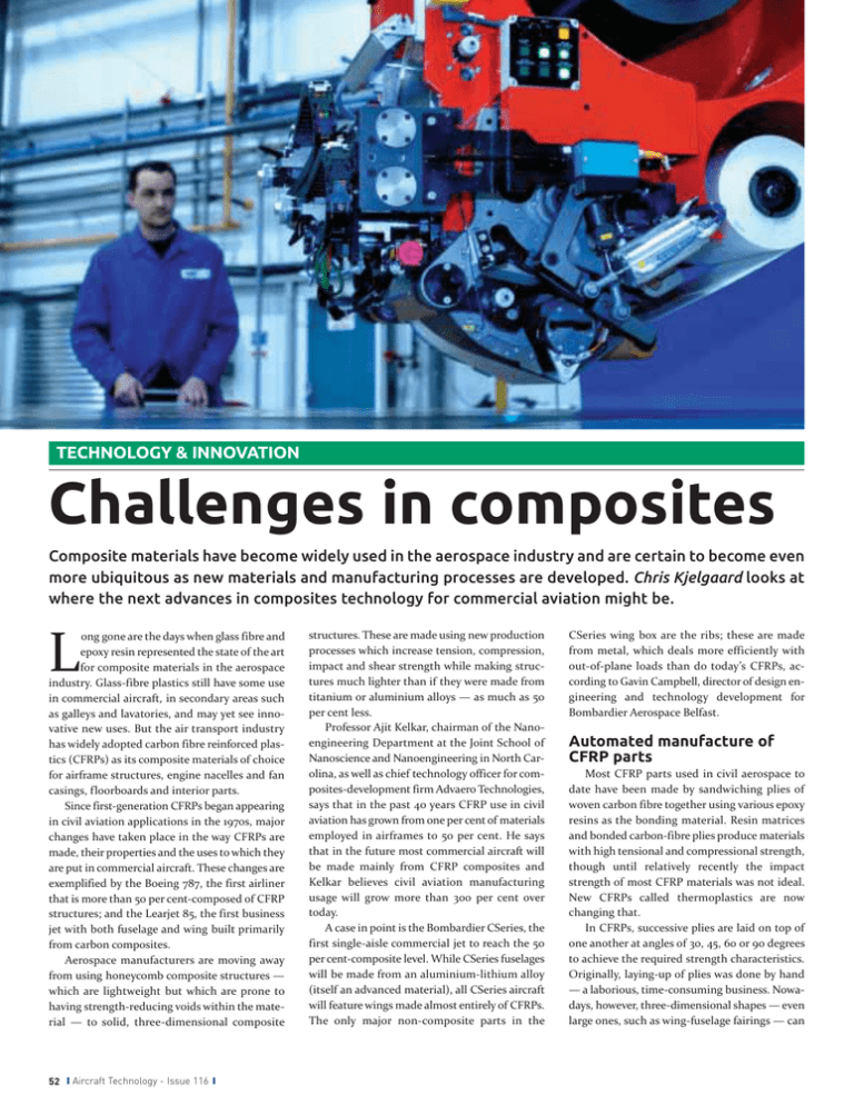
TECHNOLOGY & INNOVATION Challenges in composites Composite materials have become widely used in the aerospace industry and are certain to become even more ubiquitous as new materials and manufacturing processes are developed. Chris Kjelgaard looks at where the next advances in composites technology for commercial aviation might be. L ong gone are the days when glass fibre and epoxy resin represented the state of the art for composite materials in the aerospace industry. Glass-fibre plastics still have some use in commercial aircraft, in secondary areas such as galleys and lavatories, and may yet see innovative new uses. But the air transport industry has widely adopted carbon fibre reinforced plastics (CFRPs) as its composite materials of choice for airframe structures, engine nacelles and fan casings, floorboards and interior parts. Since first-generation CFRPs began appearing in civil aviation applications in the 1970s, major changes have taken place in the way CFRPs are made, their properties and the uses to which they are put in commercial aircraft. These changes are exemplified by the Boeing 787, the first airliner that is more than 50 per cent-composed of CFRP structures; and the Learjet 85, the first business jet with both fuselage and wing built primarily from carbon composites. Aerospace manufacturers are moving away from using honeycomb composite structures — which are lightweight but which are prone to having strength-reducing voids within the material — to solid, three-dimensional composite 52 S Aircraft Technology - Issue 116 S structures. These are made using new production processes which increase tension, compression, impact and shear strength while making structures much lighter than if they were made from titanium or aluminium alloys — as much as 50 per cent less. Professor Ajit Kelkar, chairman of the Nanoengineering Department at the Joint School of Nanoscience and Nanoengineering in North Carolina, as well as chief technology officer for composites-development firm Advaero Technologies, says that in the past 40 years CFRP use in civil aviation has grown from one per cent of materials employed in airframes to 50 per cent. He says that in the future most commercial aircraft will be made mainly from CFRP composites and Kelkar believes civil aviation manufacturing usage will grow more than 300 per cent over today. A case in point is the Bombardier CSeries, the first single-aisle commercial jet to reach the 50 per cent-composite level. While CSeries fuselages will be made from an aluminium-lithium alloy (itself an advanced material), all CSeries aircraft will feature wings made almost entirely of CFRPs. The only major non-composite parts in the CSeries wing box are the ribs; these are made from metal, which deals more efficiently with out-of-plane loads than do today’s CFRPs, according to Gavin Campbell, director of design engineering and technology development for Bombardier Aerospace Belfast. Automated manufacture of CFRP parts Most CFRP parts used in civil aerospace to date have been made by sandwiching plies of woven carbon fibre together using various epoxy resins as the bonding material. Resin matrices and bonded carbon-fibre plies produce materials with high tensional and compressional strength, though until relatively recently the impact strength of most CFRP materials was not ideal. New CFRPs called thermoplastics are now changing that. In CFRPs, successive plies are laid on top of one another at angles of 30, 45, 60 or 90 degrees to achieve the required strength characteristics. Originally, laying-up of plies was done by hand — a laborious, time-consuming business. Nowadays, however, three-dimensional shapes — even large ones, such as wing-fuselage fairings — can TECHNOLOGY & INNOVATION GKN Aerospace’s automated fibre placement machine. be created quickly and easily using numerically controlled machines which automatically apply CFRP layers in the form of tape which is oneeighth of an inch or one-quarter of an inch wide. Such machines — which can cost $10m — cut each part of tape to the right length after laying it on top of the previous ply and secure the new ply to the structure by applying heat precisely to the area of the new ply. When the CFRP part is fully built up, it is put into an autoclave and cured by heating to create chemically irreversible bonds between the resin and the carbon fibre plies. The materials made using this process are known as thermosetting CFRPs. Development of advanced machine tools for processes such as automatic tape lamination and automated fibre placement (AFP) — which correctly lay down from 24 to 72 pieces of tape at the same time — has been among the most important production innovations for thermosetting and thermoplastic CFRPs alike, says Scott Unger, group president of Ten Cate Advanced Composites & Armor North America. Thermosetting, RTM and non-crimp fabrics The thermosetting process has advantages and disadvantages. One disadvantage is that dealing with the raw materials needed to make the resin, applying exactly the right amount of slow-flowing resin to the carbon fibre plies, and making sure the resin completely fills the voids 54 S Aircraft Technology - Issue 116 S in and between the layers of ply, is difficult for non-specialists. So for many years commercial aerospace has mainly used ‘prepreg’ plies — sheets of carbon fibre already impregnated with properly applied resin — in making thermosetting CFRPs. Such prepreg materials are made by materials specialists such as Ten Cate, which supplies CFRP prepregs — and non-prepreg CFRP fabrics too — all over the world. However, most prepregs are themselves difficult to deal with. A large proportion must be refrigerated and have a shelf life of two weeks or less at room temperature. This makes them costly and sometimes inconvenient to use; and CFRPs made from prepregs don’t always have ideal properties for a particular use. Another problem, mainly of cost and production efficiency, is that aerospace-size autoclaves — large ovens whose temperatures need to be controlled precisely — are expensive and the traditional thermosetting process is time-consuming. As a result, some manufacturers have come up with their own ways of applying resin to laid-up carbon-fibre plies without needing to use prepreg materials. These techniques involve resin transfer moulding (RTM) or resin injection, into woven or non-woven layers of carbon fibre. Within the CFM International partnership, for instance, Snecma and General Electric built on GE’s earlier work in developing CFRP fan blades for the large-fan GE90 engine family by launching a dedicated technology-acquisition programme to develop 3-D CFRP fan blades and a CFRP fan case for the new, smaller LEAP engine. Making suitably strong fan blades from CFRP for smaller engines is more difficult than making strong composite fan blades for large engines, because the size of each large blade and the amount of material it requires makes it stronger. The programme produced the MASCOT demonstrator, which used a proprietary woven RTM process to knit CFRP material in three dimensions to create fan blades of the requisite size. In the LEAP engine, the weight of the fan blades — which will have metal leading edges to reduce blade erosion from bird-strikes and other foreign objects — will be only half that of a comparable fan made from metal, says Olivier Longeville, Snecma’s VP product strategy & market. Acquiring such technology is important not only for the engine itself, says Longeville. It also allows the companies within the Safran Group to study the potential benefits of using the technology elsewhere on the aircraft, for instance on landing gear units made by Snecma’s sister company Messier-Dowty. Bombardier Aerospace Belfast, meanwhile, has its own resin transfer infusion process, pumping tightly controlled amounts of resin at high pressure into carbon fibre in huge moulds to create the CSeries’ upper wing skin, lower wing TECHNOLOGY & INNOVATION skin and front and rear wing spars in single pieces. Each of the two wing skins also embodies all the associated stringers and stiffeners. “Instead of having to use fasteners, it’s all one part,” says Campbell. “The front and rear spars for the wing and the wing torque box represent a lot of [design] simplification.” Unlike GE and Snecma, whose 3-D woven RTM process is for different usages, Bombardier’s process uses an unwoven carbon-fibre fabric which represents a fairly new development in aerospace CFRP manufacturing. This “noncrimp” material, made from layers of carbon fibre laid over the top of each other at different angles but not woven together, is so named because woven carbon fibres are not maintained in the straight lines that allow them to deliver optimum performance but are “crimped” in the weaving process, whereas non-crimp fabric is not. According to Kelkar, non-crimp fabric weighs 80 grams per square metre, exactly half what a conventional woven carbon-fibre fabric would weigh, and offers three advantages. Apart from the primary weight saving, it features fewer defects than CFRP made from conventional fabric. Also, each successive ply doesn’t need to be laid on top of the previous one at a precise angle. Furthermore, non-crimp carbon fibre is usually stronger than conventional fabric — 20 to 30 per cent stronger. This means aerospace manufacturers can, say, use six plies to achieve the same structural strength for a thermoset part instead of the eight or 10 plies they would have needed using conventional fabric. Greg Bowers, president of Advaero Technologies, says the resin is heated to the point where it flows easily and fills more of the voids in the carbon fibre. At the same time the pad heats the carbon-fibre fabric to 110 degrees Fahrenheit, preventing thermal shock and so reducing the risk of other defects as the CFRP material is cured by heat from the heating pads. Thermoplastics Promising new discoveries are also being made in resin composition, says Chris Gear, VP chief engineering for GKN Aerospace, which is heavily involved in OOA work in both CFRPs and glass fibre materials. For instance, the Airbus A350 XWB will make extensive use of CFRPs whose resin matrices are from a new class of tougher, temperature-resistant resins. These resins — such as polyphenylene sulphide (PPS) and polyether ether ketone (PEEK) — will primarily be associated with thermoplastic CFRPs, a class of CFRP composite not yet widely used in civil aerospace manufacturing. Adoption of thermoplastics has been cautious because of the industry’s need for conservatism in materials qualification and airworthiness certification, but it is beginning to accelerate. CFM’s LEAP MASCOT demonstrator used a proprietary woven RTM process to knit CFRP material in three dimensions to create fan blades of the requisite size. VARTM and HVARTM The development of resin transfer moulding has produced two different methods of introducing resin into hand- or machine-laid carbon fibre structures in order for curing to take place. One is resin transfer infusion (RTI or RTM), in which resin is actively pumped into the carbon fibre in precisely controlled amounts and rates at high pressure — hundreds of pounds per square inch (PSI) — in order to fill the voids in the plies. The other method, vacuum assisted resin transfer moulding (VARTM), is less efficient in terms of filling the voids in the carbon fibre — which, for aerospace structural use, need to represent less than two per cent of total material volume — because it relies on a vacuum of minus 14 PSI to suck the resin into the carbon fibre, according to Unger. Advaero Technologies may have come up with an answer to this problem: heated vacuum assisted resin transfer moulding (HVARTM), for out-of-autoclave (OOA) manufacturing. This proprietary process, which is licensed to Advaero and for which it has a patent pending, wraps heating pads round the mould while the resin is being transferred. S Aircraft Technology - Issue 116 S 55 TECHNOLOGY & INNOVATION Bombardier Aerospace Belfast’s CSeries autoclave. Unlike thermosetting CFRPs, which cure in an oven, thermoplastics basically melt together during the manufacturing process, which takes less than 10 minutes. The material is heated, consolidated and cooled and the process is done. Thermoplastic melting creates a composite structure which can be welded together with other thermoplastic structures in joins that are as strong as the parent material itself. “They can help save weight by taking fasteners out of the equation,” says Unger. The welds also improve design strength and save on cost. Usually laser-, induction- or resistance-welding techniques are used to make these welds. A prime example is the vertical stabiliser on the Gulfstream 650, which is made of carbon/PPS Cetex thermoplastic materials from Ten Cate Advanced Composites and is induction-welded into a unified structure. Additionally, while the fuselage barrels for the A350 XWB are made from thermosetting composites, the clips on the aircraft — which Unger says represent as much CFRP volume as do the fuselage barrels themselves — all are made from Ten Cate thermoplastics. Thermoplastics have other desirable properties. They have no limits on shelf life – there is no risk of a permanent set — and can be supplied in the form of prepregs. Thermoplastics also have better impact resistance than do thermosetting CFRPs, according to Campbell. Non-structural thermoplastics have actually been around in civil 56 S Aircraft Technology - Issue 116 S aerospace for a while. An early form, used by GE, was an injection-moulded, chopped carbon/glass fibre epoxy mix, used in the CF6-80C2’s inlet guide vane and shrouds from the mid-1980s onwards. However, the aerospace industry’s need for demonstrated materials performance data and proven qualification and certification standards means prepregs won’t go out of fashion any time soon, Unger believes. Also, some prepregs — even for thermosetting composites — have a very long shelf life at room temperature. Fibre architecture and other avenues of CFRP research Other advances in CFRP technology involve using new fibre architectures such as braided or knotted carbon fibres. Senior GE materials engineers interviewed for this article say the company uses braided fibre (provided in prepreg form) and RTM infusion in manufacturing the fan blades for its new GEnx family of engines, which they describe as making “bulk” use of CFRPs. GE has saved 700lb of weight in each GEnx engine by making the fan case of CFRP composite rather than metal; and another 200lb by installing composite fan blades. (Other small parts in new GE engines, such as bushings for variable stators in some compressor stages, are made from polymer composites rather than metal; GE’s design engineers like them because they have low-wear and low-friction characteristics.) GKN Aerospace’s heavy involvement in composites research is aimed not so much at creating new materials but at developing manufacturing processes which can meet the massive forthcoming production demand for composite parts and structures on all new commercial aircraft — particularly widebodies such as the 787, which Boeing is planning to push out at the rate of 10 a month from late 2013. According to Gear, GKN is also pursuing three avenues of research into composites-reparability technologies. First is to allow easy detection of CFRP surface and under-skin damage, by means of coatings and other technologies. Second is health monitoring deep inside CFRP structures by including optical cables within carbon fibre plies to allow measurement of strains. Third is development of repair techniques allowing airlines or MROs to remove damaged areas of CFRP structures in automated fashion, rather than by hand as is the case now. Ten Cate already manufactures some CFRPs which can be inspected using non-destructive inspection techniques. However, repair and recycling of CFRPs remain considerable challenges for the future. The jury is out on who will emerge as leaders in the CFRP recycling business but OEMs, specialists such as Composites Recycling, and some aircraft tear-down companies are gearing up now for the eventual flood of CFRP parts. Some by-products of composites manufacturing, such as offcuts, are potentially usable by the aerospace industry, but TECHNOLOGY & INNOVATION (unless they are recovered whole and used for spare parts) CFRPs taken from retired aircraft and chopped up will only be suitable for nonstructural or non-aerospace secondary use. Nanoparticles: the future for CFRPs Composites repair — and the nature of CFRP materials themselves — could eventually be revolutionised if current research into the use of electrospun carbon nanotubes and nanofibres, and electrospun silica nanofibres, pays off as researchers hope. By seeding resin matrices with carbon nanotubes, which Kelkar says form the hardest materials currently known to humanity and require just a 0.15 per cent concentration within ‘Solgel’ resin made from tetraethyl ortho silicate, manufacturers could create CFRPs in which the carbon nanoparticles bind the layers of the carbon-fibre ply directly together. Just 80-120 nanometres in diameter, the electrically charged nanoparticles would bind directly to adjacent plies – each given an electrical charge in advance, to allow binding of the oppositely charged nanoparticles. This would create a “velcro” effect which would reduce reliance on the binding properties of the resin matrix, producing CFRPs that are far stronger, more impactresistant, and lighter than those known today. CFRP nanoparticle research is still in its early stages, but Bowers also sees big opportunities for carbon nanofibre patches for advanced repair of CFRP structures. Such patches would greatly increase the surface contact area available for bonding and do away with today’s Catch-22 need to delaminate additional areas in a CFRP aircraft part in order to repair a delaminated area of the structure. Ceramic matrix composites and metal matrix composites Two other families of composites will assume importance for commercial aircraft manufacturing within the next two decades. One, the advent in commercial engines — in LEAP first — of ceramic matrix composites (CMCs) made of silicon carbide fibres in a silicon carbide matrix is only a few years away. Longeville says CFM International has already tested CMC low-pressure turbine (LPT) blades in a CFM56 engine, and CMC material in the pre-combustion mixer of a CFM56-5C engine. Although the design of the LEAP engine is not yet frozen and nothing is cer- tain, it is very likely CFM International will use CMCs for some LPT blades and vanes; and potentially in the high-pressure core of the engine too as the LEAP design matures. Widespread use of metal matrix composites (MMCs) is perhaps 15 to 20 years away, with research only now beginning for commercial aviation applications. Gear says these materials, which will use carbon or metal nanotubes to strengthen metal matrices, will be twice the strength of comparable existing metal structures but only two-thirds the weight. Such materials would be ideal for, say, engine tie rod struts which transfer the engine thrust into the airframe. Gear says GKN Aerospace has already been involved in developing an MMC structure “in a nacelle environment”, in which the company “had very tight specs to meet”. Other seemingly unlikely composite pairings may lie ahead: research is underway into the properties of composite materials laced with particles of basalt or clay. Electrospun silica nanotubes may herald an advanced new generation of glass-fibre composites. Many composite-materials challenges lie ahead for aerospace companies, but equally, so do exciting times. Delivered direct to your desktop — each and every working day! ✱ News & Views ✱ Latest Technology ✱ New Products ✱ Finance Deals ✱ MRO Contracts ✱ People Moves Contact Alan Samuel today to reserve your banner ad space on Tel: +44 (0) 207 579 4846 alan.samuel@ubmaviation.com Call us for a personal demo: WichiTech Industries, Inc. (800) 776-4277 G www.wichitech.com (410) 244-1966 G FAX (410) 244-1968 1120 N. Charles Street, Suite 103, Baltimore, MD 21201, USA S Aircraft Technology - Issue 116 S 57
