Highly Active Carbon Supported Core-Shell PtNi@Pt Nanoparticles for Oxygen Reduction Reaction *
advertisement
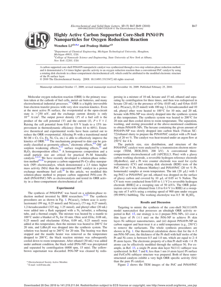
Electrochemical and Solid-State Letters, 13 共5兲 B47-B49 共2010兲 B47 1099-0062/2010/13共5兲/B47/3/$28.00 © The Electrochemical Society Highly Active Carbon Supported Core-Shell PtNi@Pt Nanoparticles for Oxygen Reduction Reaction Wenzhen Lia,b,*,z and Pradeep Haldara,b a Department of Chemical Engineering, Michigan Technological University, Houghton, Michigan 49931, USA College of Nanoscale Science and Engineering, State University of New York at Albany, New York 12203, USA b A carbon supported core-shell PtNi@Pt nanoparticle catalyst was synthesized through a two-step solution-phase reduction method, and it demonstrated a 5.4 times higher specific activity to an oxygen reduction reaction than a conventional Pt/C catalyst by using a rotating disk electrode in a three-compartment electrochemical cell, which could be attributed to the modified electronic structure of the Pt surface layer. © 2010 The Electrochemical Society. 关DOI: 10.1149/1.3313347兴 All rights reserved. Manuscript submitted October 17, 2009; revised manuscript received November 16, 2009. Published February 25, 2010. Molecular oxygen reduction reaction 共ORR兲 is the primary reaction taken at the cathode of fuel cells, metal–air batteries, and many electrochemical industrial processes.1-4 ORR is a highly irreversible four-electron transfer process with very slow reaction kinetics. Even at the most active Pt surface, the overpotential at the open-circuit state is ⬎250 mV, and the exchange current density is only 10−9 A/cm2. The output power density 共 P兲 of a fuel cell is the product of the cell potential 共V兲 and the current 共I兲, P = V ⫻ I. Raising the cell potential from 0.65 to 0.9 V leads to a 15% improvement in thermodynamic efficiency 共from 44 to 60%兲. Extensive theoretical and experimental works have been carried out to reduce the ORR overpotential. Alloying Pt with a transitional metal M 共M = Cr, Co, Fe, Ni, Cu, etc.兲 is able to effectively improve the kinetics of ORR.4-18 The mechanisms proposed to date can be generally classified as geometric effects,5 electronic effects,6-8 OH− adsorption weakening effects,9-13 surface roughening effects,14 and H2O2 decomposition effect.15 A homogeneous composition and a small particle size are critical for practical Pt–M bimetallic catalysts.2,4,12 We have recently developed a solution-phase reduction method19,20 to prepare a carbon supported Pt–Co alloy nanoparticle 共NP兲 electrocatalyst, which demonstrated a 2.5 times higher mass activity 共MA兲 than the conventional Pt/C catalyst in a proton exchange membrane fuel cell.20 In this article, we modified this solution-phase method to prepare carbon supported PtNi-core Ptshell 共PtNi@Pt/C兲 NPs as electrocatalysts and tested its ORR activity in a three-compartment electrochemical cell. Experimental The synthesis of PtNi@Pt/C was based on a solution-phase reduction method invented by IBM researchers.21,22 The synthesis procedures are as shown in Fig. 1. Pt共acac兲2 共where acac is acetylacetonate兲 共99 mg, 0.25 mmol兲 and Ni共acac兲2 共73 mg, 0.27 mmol兲, 1,2-hexadecanediol 共325 mg, 1.25 mmol兲, and phenyl ether 共20 mL兲 were added into a flask equipped with a N2 in/outlet, a refluxing tube, and a thermal couple. The mixture was heated by a mantle to 100°C under a blanket of N2 for 10 min. Oleic acid 共OAc, 0.08 mL, 0.25 mmol兲 and oleylamine 共OAm, 0.09 mL, 0.25 mmol兲 were added at this temperature, then the mixture was heated to 200°C for 20 min, and LiBet3H was dropped into the synthesis system. The solution was heated up to 260°C for 20 min. The heating was then stopped and the mantle heater was removed as the temperature dropped to 200°C, the black reaction mixture was subsequently cooled down to room temperature. After ethanol 共30 mL兲 was added under ambient condition, the black solid 共PtNi-NP兲 was precipitated and separated by centrifugation 共6000 rpm, 15 min兲. The yellowbrown supernatant was discarded. PtNi-NP was cleaned by redis- * Electrochemical Society Active Member. z E-mail: wzli@mtu.edu persing in a mixture of 10 mL hexane and 15 mL ethanol and separating by centrifugation for three times, and then was redispersed in hexane 共20 mL兲 in the presence of OAc 共0.05 mL兲 and OAm 共0.03 mL兲. Pt共acac兲2 共0.25 mmol兲 with 100 mg 1,2-hexadecanediol and 10 mL phenyl ether were heated to 100°C for 10 min, and 20 mL hexane with PtNi-NP was slowly dropped into the synthesis system at this temperature. The synthesis system was heated to 200°C for 20 min and then cooled down to room temperature. The separation, washing, and storing proceeded at the above-mentioned conditions to obtain PtNi@Pt NPs. The hexane containing the given amount of PtNi@Pt-NP was slowly dropped into carbon black 共Vulcan XC72兲/ethanol slurry to prepare the PtNi@Pt/C catalyst with a Pt loading of 20 wt %. The catalyst was heat-treated under an argon flow at 250°C for 4 h. The particle size, size distribution, and structure of the PtNi@Pt/C catalyst were analyzed by a transmission electron microscope 共TEM, JEOL2010, 200 kV兲. A conventional threecompartment electrochemical cell 共AFCELL3, Pine兲 with a glassy carbon working electrode, a reversible hydrogen reference electrode 共Hydroflex兲, and a Pt wire counter electrode was used for cyclic voltammetry 共CV兲 and rotating disk electrode 共RDE兲 tests of the Pt/C 共20 wt % Pt, Johnson Matthey兲 and PtNi@Pt/C 共20 wt % Pt, homemade兲 samples at room temperature. The ink 共20 L兲 with 1 mg Pt/C/ or PtNi@Pt/C per mL ethanol was dropped on the surface of glassy carbon and covered by 10 L of 0.05 wt % Nafion. The CV tests were conducted from 0.05 to 1.1 V 关vs reversible hydrogen electrode 共RHE兲兴 at a sweeping rate of 50 mV/s. The ORR polarization curves were obtained from 1.0 to 0.4 V 共vs RHE兲 at a sweeping rate of 5 mV/s using a rotating speed of 900 rpm under oxygen 共99.999%兲 bubbling. The working electrolyte was 0.5 M H2SO4. Results and Discussion Targeting to mimic the synthesis of the core-shell Ni共111兲@Pt model nanocatalyst that possesses an ultrahigh ORR activity reported in Ref. 13, our strategy is to i兲 prepare PtNi NPs, 共ii兲 coat a thin layer of Pt 共ⱕ1 nm兲 on the PtNi-NP to achieve Pt skin layer–Ni sublayer nanostructures, and 共iii兲 deposit PtNi@Pt-NP on carbon support and heat-treat it at a mild temperature 共e.g., 250°C兲 to remove the surfactants. The whole synthesis procedures are shown in Fig. 1. Our theoretical calculation shows that for the 4–5 nm PtNi-NP core, the thickness of the Pt shell with half moles of the Pt and Ni cores is between 0.5 and 1.0 nm, which are equal to 2–4 Pt atom layers. The electronic property of a thin Pt shell with ⬍4 Pt atoms can be effectively modified through the sublayer Ni. For example, in Ref. 13, a single Pt atom skin layer Ni共111兲 sublayer was synthesized. In Ref. 7 and 8, less than 1 nm 共4 atom layer兲 Pt surface and Fe/Co/Ni sublayer structure was prepared. Both of these nanostructured catalysts exhibit a very high ORR specific activity 共SA兲 than the pure Pt catalyst. Figure 2 shows the TEM images of the Pt/C and PtNi@Pt/C Downloaded 28 Dec 2010 to 141.219.211.64. Redistribution subject to ECS license or copyright; see http://www.ecsdl.org/terms_use.jsp Electrochemical and Solid-State Letters, 13 共5兲 B47-B49 共2010兲 B48 0.5M H2SO4 Current density / mA.cm -2 1.0 Pt/C (20wt%-Pt) 0.5 0.0 PtNi@Pt/C (20wt%-Pt) -0.5 -1.0 -1.5 -2.0 0.0 0.2 0.4 0.6 0.8 1.0 1.2 Potential / V vs. RHE Figure 3. 共Color online兲 Cyclic voltammograms of Pt/C and PtNi@Pt/C catalysts in 0.5 M H2SO4. Sweep rate: 50 mV/s, room temperature. Figure 1. 共Color online兲 Synthesis procedures of the solution-phase method for preparing carbon supported core-shell PtNi@Pt NP catalyst. catalysts. The commercial Pt/C catalyst has small Pt NPs with a size distribution of 2–5 nm homogeneously deposited on the carbon support. The average particle size of Pt NPs is 3.4 nm. For the coreshell PtNi@Pt/C catalyst, the particle size distribution is 5–8 nm and centered at 6.2 nm. The core-shell NPs are also uniformly deposited a b on the carbon surface. A few small NPs with sizes of 3–4 nm can be observed, and they are uncoated PtNi-NP and pure Pt-NP. Further work will be focused on optimizing a Pt coating process 共step 2兲 to achieve core-shell PtNi@Pt particles with uniform compositions. The CV curves of Pt/C and PtNi@Pt/C are shown in Fig. 3. The electrochemical surface areas 共ECSAs兲 of Pt/C and PtNi@Pt/C are 54 and 23 m2 /g, respectively. The chemical surface areas 共CSAs兲 of the two catalysts are 82 and 45 m2 /g. The Pt utilization can be expressed as the ratio of ECSA over CSA,15 and they are 65.9 and 51.1% for the Pt/C and PtNi@Pt/C catalyst. The estimated surface composition of PtNi@Pt-NP is 79% Pt, which is higher than that of the commercial PtNi/C and Pt3Ni/C 共20 and 70% Pt on the surface, respectively兲, as reported in Ref. 12. This indicates that the PtNi@Pt/C catalyst has a Pt-rich shell; the formation can be logically attributed to the adopted two-step solution-phase reduction synthesis approach, through which more Pt can be coated on the PtNi-NP surface. In addition, surface segregation can be facilitated during the thermal treatment, leading to the Pt-rich structure. The activity of the ORR on the two catalysts was evaluated using RDE in a three-compartment electrochemical cell, as shown in Fig. 4. The PtNi@Pt/C catalyst has a higher diffusion-limited current density id than Pt/C. The kinetic current density ik can be calculated by Eq. 1, where io is the observed current that can be directly obtained from the ORR curve ik = 共id ⫻ io兲/共id − io兲 关1兴 The MA of the catalyst is therefore calculated by Eq. 2 MA = ik /electrode mass loading 关2兴 The electrode mass loading is 20.7 g Pt/cm . At 0.9 V 共vs RHE兲, the MA of PtNi@Pt/C is 29.1 mA/mg Pt, which is 2.3 times higher than that of Pt/C 共12.7 mA/mg Pt兲. The SA of the catalyst can be calculated by Eq. 3 2 c d 关3兴 SA = MA/ECSA Because PtNi@Pt/C has a smaller ECSA than Pt/C 共23 vs 54 m /g兲, the SA of PtNi@Pt/C is 5.4 times higher than Pt/C 共126.5 vs 23.5 A/cm2兲. The reported ORR activity is lower than the reported data in Ref. 4 and 12. This is because 共i兲 we used 0.5 M H2SO4, an anion-adsorption electrolyte; the current is lower than that obtained in the 0.1 M HClO4 electrolyte, and 共ii兲 we applied the cathodic voltage sweep 共from 1.0 to 0.4 V兲 to collect the ORR current, which was lower than the current collected based on the anodic voltage sweep 共e.g., from 0.4 to 1.0 V兲. Therefore, the comparison of the ORR activity on the two catalysts still holds 2 Figure 2. TEM images of Pt/C 关共a兲 and 共b兲兴 and PtNi@Pt/C 关共c兲 and 共d兲兴 catalysts. Downloaded 28 Dec 2010 to 141.219.211.64. Redistribution subject to ECS license or copyright; see http://www.ecsdl.org/terms_use.jsp Electrochemical and Solid-State Letters, 13 共5兲 B47-B49 共2010兲 0.0 In the current study, we introduced a wet chemical synthesis route to deliberately prepare a Ni–Pt core-shell nanostructure, which demonstrated a higher SA toward ORR than Pt/C. This synthesis strategy could potentially be extended to prepare many other core-shell structures as efficient catalysts for a wide spectrum of reactions, such as Au@Pd for formic acid oxidation and Ru@Pt for preferential oxidation of CO in hydrogen. 0.5M H2SO4, 900 rpm -2 -0.5 Current density / mA.cm B49 -1.0 -1.5 Conclusions In this article, a modified solution-phase reduction method was used to prepare a PtNi@Pt/C catalyst, which has a mean particle size of 6.2 nm and uniform Pt dispersion on carbon black support. The PtNi@Pt/C catalyst demonstrated a 5.4 times higher SA than the Pt/C catalyst, which can be attributed to its modified electronic structure by the underlying Ni sublayer. -2.0 -2.5 Pt/C (20wt%-Pt) -3.0 PtNi@Pt/C (20wt%-Pt) Acknowledgments -3.5 0.3 0.4 0.5 0.6 0.7 0.8 0.9 1.0 Potential / V vs. RHE Figure 4. 共Color online兲 Polarization curves for the ORR on Pt/C and PtNi@Pt/C catalysts by RDE in 0.5 M H2SO4. Sweep rate: 5 mV/s, anodic sweep, room temperature. valid: The core-shell PtNi@Pt/C catalyst demonstrated a 5.4 times higher ORR SA than commercial Pt/C. As shown in Ref. 4, the SA of Pt–Co/C 关Tanaka Kikinzoku Kogyo K.K., Japan 共TKK兲兴 is −2 , which is 2.6 times higher than that of Pt/C 共40 wt 550 A cmPt −2 . Elegant work on model catalysts has %, TKK兲 of 210 A cmPt demonstrated that core-shell Ni–Pt can greatly improve the ORR SA.7,13 Various base metal 共Fe, Co, Ni, Cu, etc.兲 core Pt shell nanostructures have shown improved ORR activity. For example, Pt single-layer catalysts prepared by an underpotential deposition technique exhibit a high ORR activity.16,17 Dealloyed Pt–Cu/C was reported to have an enhanced ORR activity.18 A Pt skin layer–Ni共111兲 sublayer model catalyst demonstrates a 90 times higher SA than the conventional Pt/C catalyst.13 A Pt–Fe thin-film model catalyst 共⬍1 nm Pt skin layer and 3–4 nm Fe sublayer兲 demonstrates a 20 times higher ORR activity than the Pt thin film through a modified electronic structure of Pt by the sublayer base metal Fe.7,8 The electrocatalytic ORR activity enhancement can be attributed to the modified electronic structure of the surface Pt through the underlying M 共Ni, Co, and Fe兲 sublayer. Toda et al. proposed that the increased 5d vacancies of Pt lead to an increased 2 electron donation from O2 to the surface Pt, resulting in an increased O2 adsorption and weakening of the O–O bond, thus facilitating the ORR kinetics.7,8 Stamenkovic et al., however, proposed that less anion − 共e.g., SO2− 4 and OH 兲 adsorption on modified Pt electronic structure 共d-band center position兲 is the main cause of increasing the number of active sites for O2 adsorption and improving the ORR activity.13 The work was partially supported by MTU start-up package D90925. Michigan Technological University assisted in meeting the publication costs of this article. References 1. E. Yeager, Electrochim. Acta, 29, 1527 共1984兲. 2. T. R. Ralph and M. P. Hogarth, Platinum Met. Rev., 46, 3 共2002兲. 3. P. N. Ross, Handbook of Fuel Cells: Fundamentals, Technology and Applications, Vol. 2, p. 464, John Wiley & Sons, New York 共2003兲. 4. H. A. Gasteiger, S. S. Kocha, B. Sompalli, and F. T. Wagner, Appl. Catal. B, 56, 9 共2005兲. 5. V. Jalan and E. J. Taylor, J. Electrochem. Soc., 130, 2299 共1983兲. 6. S. Mukerjee, S. Srinivasan, M. P. Soriaga, and J. McBreen, J. Electrochem. Soc., 142, 1409 共1995兲. 7. T. Toda, H. Igarashi, H. Uchida, and M. Watanabe, J. Electrochem. Soc., 146, 3750 共1999兲. 8. T. Toda, H. Igarashi, and M. Watanabe, J. Electroanal. Chem., 460, 258 共1999兲. 9. V. Stamenkovic, T. J. Schmidt, P. N. Ross, and N. M. Markovic, J. Phys. Chem. B, 106, 11970 共2002兲. 10. V. Climent, N. M. Markovic, and P. N. Ross, J. Phys. Chem. B, 104, 3116 共2000兲. 11. N. M. Markovic, H. A. Gasteiger, and P. N. Ross, J. Phys. Chem., 100, 6715 共1996兲. 12. U. A. Paulus, A. Wokaun, G. G. Scherer, T. J. Schmidt, V. Stamenkovic, V. Radmilovic, N. M. Markovic, and P. N. Ross, J. Phys. Chem. B, 106, 4181 共2002兲. 13. V. Stamenkovic, B. Fowler, B. S. Mun, G. F. Wang, P. N. Ross, C. A. Lucas, and N. M. Markovic, Science, 315, 493 共2007兲. 14. M. T. Paffett, J. G. Beery, and S. Gottefeld, J. Electrochem. Soc., 135, 1431 共1988兲. 15. W. Z. Li, W. J. Zhou, Z. H. Zhou, H. Q. Li, B. Zhou, G. Q. Sun, and Q. Xin, Electrochim. Acta, 49, 1045 共2004兲. 16. S. R. Brankovic, X. Wang, and R. R. Adzic, Surf. Sci. Lett., 474, L173 共2001兲. 17. Z. L. Zhang, M. B. Vukmirovic, Y. Xu, M. Mavrikakis, and R. R. Adzic, Angew. Chem., Int. Ed., 44, 2132 共2005兲. 18. S. Koh and P. Strasser, J. Am. Chem. Soc., 129, 12624 共2007兲. 19. W. Z. Li and P. Haldar, Electrochem. Commun., 11, 1195 共2009兲. 20. W. Z. Li, Z. W. Chen, L. B. Xu, and Y. Yan, J. Power Sources, 195, 2534 共2010兲. 21. S. H. Sun, C. B. Murray, D. Weller, L. Folks, and A. Moser, Science, 287, 1989 共2000兲. 22. S. H. Sun, S. Anders, T. Thomson, J. E. E. Baglin, M. F. Toney, H. F. Hamann, C. B. Murray, and B. D. Terris, J. Phys. Chem. B, 107, 5419 共2003兲. Downloaded 28 Dec 2010 to 141.219.211.64. Redistribution subject to ECS license or copyright; see http://www.ecsdl.org/terms_use.jsp
