Lab 11: Sequence Detector
advertisement

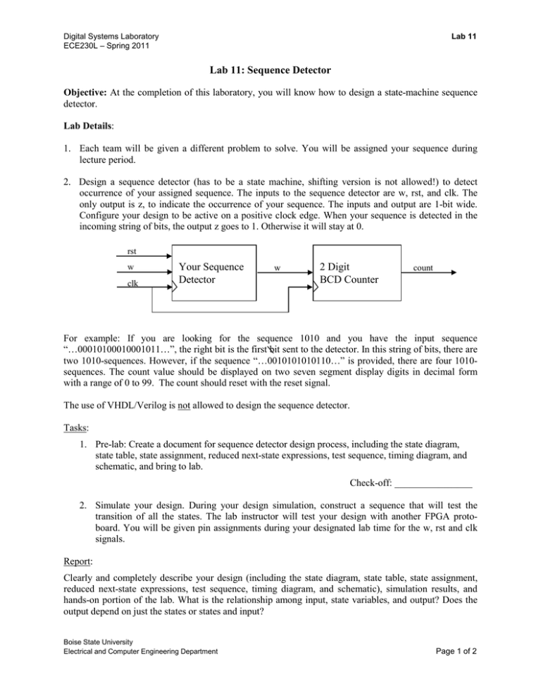
Lab 11 Digital Systems Laboratory ECE230L – Spring 2011 Lab 11: Sequence Detector Objective: At the completion of this laboratory, you will know how to design a state-machine sequence detector. Lab Details: 1. Each team will be given a different problem to solve. You will be assigned your sequence during lecture period. 2. Design a sequence detector (has to be a state machine, shifting version is not allowed!) to detect occurrence of your assigned sequence. The inputs to the sequence detector are w, rst, and clk. The only output is z, to indicate the occurrence of your sequence. The inputs and output are 1-bit wide. Configure your design to be active on a positive clock edge. When your sequence is detected in the incoming string of bits, the output z goes to 1. Otherwise it will stay at 0. rst w clk Your Sequence Detector w 2 Digit BCD Counter count For example: If you are looking for the sequence 1010 and you have the input sequence “…00010100010001011…”, the right bit is the first bit sent to the detector. In this string of bits, there are two 1010-sequences. However, if the sequence “…0010101010110…” is provided, there are four 1010sequences. The count value should be displayed on two seven segment display digits in decimal form with a range of 0 to 99. The count should reset with the reset signal. The use of VHDL/Verilog is not allowed to design the sequence detector. Tasks: 1. Pre-lab: Create a document for sequence detector design process, including the state diagram, state table, state assignment, reduced next-state expressions, test sequence, timing diagram, and schematic, and bring to lab. Check-off: ________________ 2. Simulate your design. During your design simulation, construct a sequence that will test the transition of all the states. The lab instructor will test your design with another FPGA protoboard. You will be given pin assignments during your designated lab time for the w, rst and clk signals. Report: Clearly and completely describe your design (including the state diagram, state table, state assignment, reduced next-state expressions, test sequence, timing diagram, and schematic), simulation results, and hands-on portion of the lab. What is the relationship among input, state variables, and output? Does the output depend on just the states or states and input? Boise State University Electrical and Computer Engineering Department Page 1 of 2 Digital Systems Laboratory ECE230L – Spring 2011 Lab 11 Deliverables: Check-off: TA to review design process document at beginning of lab period Submission: Due by Midnight Thursday 4/21/2011 Email: To: ece230lreport@gmail.com cc: your team partner Subject: Lab10_TeamX report (X is your team no.) Attachment: Lab10_TeamX.zip (contents as listed below) Attachment: (must be zip format – no others accepted) Contents of zip file: 1. Report File: \Lab10_TeamX_Report.pdf Report Content (create in Word using template previously provided) 1. Team number, team member names, lab no. and name 2. The complete FSM design process 3. Type and number of chips used 4. Schematic diagram 5. Simulation waveform 6. Results and reflections Clearly and completely describe your design as described above, and trade-offs that you have made. After report has been created in Word, create a pdf and then zip. Boise State University Electrical and Computer Engineering Department Page 2 of 2


