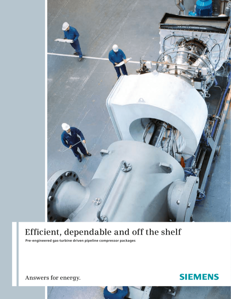
Efficient, dependable and off the shelf
Pre-engineered gas-turbine driven pipeline compressor packages
Answers for energy.
Siemens Pipeline Compressor Packages
Siemens Pipeline Compressor Packages
are pre-engineered gas turbine compressor packages for pipeline applications.
These combine our standard ranges
of Siemens Gas Turbines (SGT TM) and
Siemens Turbocompressors (STC TM)
optimized to provide you with the best
technical and cost efficient solution
for your transmission and distribution
needs. The compressors cover a flow
range of 5,000 – 38,000 actual m3 / hr
(3,000 – 22,500 ACFM) with pressure
ratios up to 2.0.
Gas turbines with powers up to 13 MW
(ISO) offer the best efficiency in their
class with Siemens world beating dry
low emissions or standard combustion
systems.
Siemens Pipeline Compressor Packages
come with a range of pre-engineered
standard options to meet customerspecific
requirements.
Benefits
Single-source responsibility
Cost efficient solutions
Short lead-times
Available documentation
- Package drawings
- Foundation details
- P&ID’s
- Torsional and lateral critical
speed report
Proven technology
Condition monitoring by electronic
data exchange
On-condition maintenance
In-field serviceability
Long-term service agreements
Siemens Pipeline Compressor Packages
are available in three sizes based upon
the SGT-100, SGT-200 and the SGT-400
gas turbines.
Compressors are matched to the gas
conditions and the gas turbine speed to
provide optimum performance.
Selections can be focused on customerspecific requirements such as maximum
efficiency or maximum range or other
operating parameters.
General description
Gas Turbines
Compressors
Package
Air Compressor
Multi-stage axial flow
Casing
Forged steel barrel type
Common casing for 1- or 2-stage rotor
Horizontally opposed inlet and
discharge nozzles (can be left- or
right-handed)
Two end heads with shear ring
Lubrication
Common mineral oil system for gas
turbine and compressor
Reservoir integral with the gas turbine
baseplate
Combustion
Reverse flow tubular combustion
chambers
Conventional or dry low emissions
(DLE) combustion system
High-energy ignition
Turbines
1- or 2-stage overhung air-cooled
compressor turbine
2-stage high-efficiency free power
turbine with interlocking blades for
mechanical integrity
Cast stators either segmental or
complete rings
Fuel System
Natural gas
Optional dual fuel
Bearings
Both rotors have tilting pad journal
and thrust bearings
Starting
Via the auxiliary gearbox mounted
at the inlet end
Variable-speed AC motor for
SGT-100 and SGT-200
E-driven hydraulic turbine starter
system for SGT-400
Option for air/gas motor
Rotor
Solid forged steel shaft
Shrunk on 3-D type impellers
Stator
Forged diaphragms
Fabricated inlet guide vane
Cast discharge volute
Bearings
Tilting pad journal and thrust bearings
Seals
Tandem dry gas seals
Coupling
Dry metallic element flexible coupling
Non-sparking (brass) coupling guard
Controls
Fully integrated PLC-based compressor
and gas turbine control system
Anti-surge control
Process and vent valve sequencing
Governing
Vibration and axial position monitoring
Temperature monitoring
Load sharing on multi-engine sites
(option)
Enclosure
Indoor enclosure (option)
Outdoor enclosure (option)
Customer Support
Global support network
Customer support managers
Round-the-clock specialist helpdesk
Remote monitoring and troubleshooting via Electronic Data Exchange
Network (EDEN) system
Diagnostic support from worldwide
service centers
SPCP-100 package including auxiliaries such
as lubrication system and seal gas system.
SPCP-100
Main characteristics:
ISO power 4.92 MW (6,600 bhp)
Nominal speed 13,000 rpm
Max. compressor casing pressure
110 bar g (1,595 psig)
Nozzle sizes 20 inch – class 900
6,000
Inlet air temperature° C
-15° C
5,500
Power limit
0° C
Power turbine output [kW]
The package is designed for the application of a standardized STC-SV type
compressor matching the SGT-100 gas
turbine. Aerodynamic parts are tailormade design in order to get highest
efficiency and the best operating range
for the customer-specific application.
4,830 kW
5,000
11,000
15° C
4,500
30° C
11,500
4,000
45° C
3,500
12,000
3,000
Specific heat input kJ/kWh
12,500
2,500
13,000
2,000
14,000
1,500
1,000
8,000
16,000
9,000
10,000
11,000
12,000
13,000
14,000
Power turbine speed [rpm]
The SGT-100 performance curve shows the gas turbine power as a function of the ambient
temperature and speed with a 100 mm H2 O inlet loss and 75 mm H2 O exhaust loss.
Overall
dimensions
SPCP-100
Length
mm
inches
9,224
363.15
30,000
Width
mm
inches
2,650
104.3
25,000
2,818
111
Weight
kg
lbs
40,000
88,200
Baseplate design
Single baseplate
under compressor
and gas turbine
5,000
10,000
15,000
20,000
80
70
2-stage
60
20,000
1-stage
50
15,000
40
10,000
Psuc = 30 bar
40 bar
50 bar
65 bar
5,000
0
0
2,000
4,000
6,000
8,000
10,000
30
20
10
0
12,000
Actual compressor suction flow rate [ft 3 / min]
The STC pipeline compressor selection chart shows the compressor head versus the suction
inlet flow. Two different application areas for the individual design points are shown.
Compressor head [kJ / kg]
mm
inches
0
Compressor head [ft-lbf / lb]
Height
Actual compressor suction flowrate [m3 / hr]
SPCP-200
Main characteristics:
ISO power 7.68 MW (10,300 bhp)
Nominal speed 10,950 rpm
Max. compressor casing pressure
110 bar g (1,595 psig)
Nozzle sizes 24 inch – class 900
9,000
Inlet air temperature° C
-15° C
Power limit
-5° C
8,000
Power turbine output [kW]
The package is designed for the application of a standardized STC-SV type
compressor matching the SGT-200 gas
turbine. Aerodynamic parts are tailormade design in order to get highest
efficiency and the best operating range
for the customer-specific application.
7,496 kW
0° C
15° C
11,000
30° C
11,500
7,000
6,000
40° C
12,000
5,000
12,500
13,000
4,000
14,000
3,000
Specific heat input kJ / kWh
2,000
7,000
8,000
9,000
10,000
11,000
12,000
Power turbine speed [rpm]
The SGT-200 performance curve shows the gas turbine power as a function of the ambient
emperature and speed with a 100 mm H2 O inlet loss and 75 mm H2 O exhaust loss.
Overall
dimensions
SPCP-200
Length
mm
inches
10,715
421.85
30,000
Width
mm
inches
2,650
104.3
25,000
3,010
118.5
Weight
kg
lbs
53,900
118,850
Baseplate design
Single baseplate
under compressor
and gas turbine
5,000
10,000
15,000
20,000
25,000
80
70
2-stage
60
20,000
50
1-stage
15,000
40
10,000
30
Psuc = 30 bar
20
40 bar
50 bar
65 bar
5,000
0
0
2,000
4,000
6,000
8,000
10,000
12,000
14,000
10
0
16,000
Actual compressor suction flow rate [ft 3 / min]
The STC pipeline compressor selection chart shows the compressor head versus the suction
inlet flow. Two different application areas for the individual design points are shown.
Compressor head [kJ / kg]
mm
inches
0
Compressor head [ft-lbf / lb]
Height
Actual compressor suction flowrate [m3 / hr]
SPCP-400
Main characteristics:
ISO power 13.4 MW (18,000 bhp)
Nominal speed 9,500 rpm
Max. compressor casing pressure
125 bar g (1,812 psig)
Nozzle sizes 30 inch – class 900
Lines in blue apply to standard size PT nozzle.
Lines in orange apply to large (high ambient) PT nozzle.
16,000
Inlet air temperature° C
Power limit
-15° C
15,000
9,750
0° C
13,122 kW
14,000
Power turbine output [kW]
The package is designed for the application of a standardized STC-SV type
compressor matching the SGT-400 gas
turbine. Aerodynamic parts are tailormade design in order to get highest
efficiency and the best operating range
for the customer-specific application.
10,000
13,000
15° C
10,250
12,000
30° C
30° C
11,000
10,500
10,500
40° C
10,750
10,000
11,000
9,000
50° C
11,500
Specific heat input kJ/kWh
12,000
8,000
7,000
12,500
6,000
13,000
5,000
4,000
5,000
6,000
7,000
8,000
9,000
10,000
Power turbine speed [rpm]
The SGT-400 performance curve shows the gas turbine power as a function of the ambient
temperature and speed with a 100 mm H2 O inlet loss and 75 mm H2 O exhaust loss.
Overall
dimensions
SPCP-400
Length
mm
inches
10,787
424.7
30,000
Width
mm
inches
2,750
108.3
25,000
Height
mm
inches
3,448
135.75
Weight
kg
lbs
72,800
160,525
5,000 10,000 15,000
20,000
25,000
30,000
35,000
40,000
80
2-stage
70
60
20,000
1-stage
50
15,000
40
10,000
Psuc = 30 bar
40 bar
50 bar
65 bar
5,000
0
30
20
10
0
0
4,000
8,000 12,000
16,000
20,000
24,000
Actual compressor suction flow rate [ft 3 / min]
The STC pipeline compressor selection chart shows the compressor head versus the suction
inlet flow. Two different application areas for the individual design points are shown.
Compressor head [kJ / kg]
Seperate baseplates
under compressor
and gas turbine
0
Compressor head [ft-lbf / lb]
Baseplate design
Actual compressor suction flowrate [m3 / hr]
Conversion charts
Standard vs. actual volume flow
Actual compressor suction flow rate [m3 / hr]
10,000
20,000 30,000
V norm [mmscfd]
40,000
50,000
p suc = 65 bar
1,800
p suc = 55 bar
1,600
p suc = 50 bar
2,000,000
1,400
1,500,000
p suc = 40 bar
1,200
1,000
p suc = 30 bar
1,000,000
800
V norm [Nm3 / hr]
0
2,000
600
500,000
400
200
0
0
5,000
10,000 15,000
20,000
25,000
0
30,000
Actual compressor suction flow rate [ft 3 / min]
Compressor head vs. pressure ratio
100
40° C
20° C
30,000
0° C
80
suction
temperature
25,000
60
20,000
15,000
40
10,000
20
5,000
0
0
0
1.1
1.2
1.3
1.4
1.5
1.6
1.7
1.8
Pressure ratio [P 2 /P1]
1.9
2.0
2.1
2.2
2.3
Compressor head [kJ / kg]
Compressor head [ft-lbf / lb]
35,000
The two diagrams allow an approximation of
the “Actual Compressor Suction Flow Rate” and
the “Compressor Head” required for the selection
charts shown for the individual packages.
Published by and copyright © 2008:
Siemens AG
Energy Sector
Freyeslebenstrasse 1
91058 Erlangen, Germany
Siemens AG
Energy Sector
Oil & Gas
Wolfgang-Reuter-Platz
47053 Duisburg, Germany
Siemens Energy Inc.
10730 Telge Road
Houston, Texas 77095, USA
For more information, please contact
our Customer Support Center.
Phone:+49 180 524 70 00
Fax: +49 180 524 24 71
(Charges depending on provider)
E-mail: support.energy@siemens.com
Oil & Gas Division
Order No. E50001-G440-A105-V1-4A00
Printed in Germany
Dispo 05400, c4bs 1389, 4498 WS 11083
Printed on elementary chlorine-free
bleached paper.
All rights reserved.
Trademarks mentioned in this document
are the property of Siemens AG, its affiliates,
or their respective owners.
Subject to change without prior notice.
The information in this document contains
general descriptions of the technical options
available, which may not apply in all cases.
The required technical options should therefore
be specified in the contact.
www.siemens.com /energy


