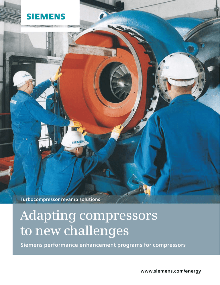
Turbocompressor revamp solutions
Adapting compressors
to new challenges
Siemens performance enhancement programs for compressors
www.siemens.com/energy
The optimal strategy to
meet new requirements
Siemens compressor performance enhancement
protects investments and creates value added.
2
In many industries rotating equipment is the backbone of
core processes. This is why compressors and their drives
are designed to operate continually over a long period
of time. However, market conditions can easily change,
and so can best operational practices and framework
conditions. This means that equipment modifications
become necessary.
Revamp solutions from Siemens:
customized design
state-of-the-art compressor technology
the know-how of a market leader
In such cases, the replacement of main compressor
components or even entire compressors and drives is
usually one of the major cost factors. A revamp can be
a cost-effective solution enabling existing machinery
to work more efficiently, meet new requirements, and
conform to new emission reduction guidelines.
unique knowledge of the entire train history
with OEM equipment
While some main compressor components are replaced
during a revamp, many existing parts and ancillary
equipment can be reused. This minimizes costs and
ensures a relatively short shutdown period.
a unique service partnership
outstanding experience in revamping all types
of turbocompressors
strong rotor dynamic engineering capabilities
Siemens, a global powerhouse in compressor and turbine
technology, has the expertise and experience to provide
revamp solutions for compressors as well as for entire
trains as a one-stop solution.
3
Welding of an impeller
Rotor installation of an axial radial turbocompressor
Knowledge that pays off
Familiarity with the individual machine and its entire
history is what puts the Siemens experts one step ahead.
Every plant has specific technical, operational, financial,
and environmental requirements. This is why knowing
the entire history of an individual machine is a real
advantage – just like the wide experience in revamping
compressors of all types the Siemens experts have
acquired over several decades.
This rare combination makes possible unique insights
that enable implementing the latest state-of-the-art
technology, precisely identify hidden potential, and
enhance both short and long-term turbomachinery
performance.
There is a single point of contact for the customer for
all questions, as each revamp project is assigned to a
dedicated service team. This ensures that the entire project
keeps running like clockwork. Be it replacement parts,
professional advice on delivery, and installation or project
coordination: the Siemens expert in charge is just a phone
call away.
4
Single-shaft compressor rotating element ready for installation
Precise planning is half the story
The adaptation of a compressor is a cost-efficient way
of answering to new process conditions. However, there
are several factors to be considered in order to make
the investment pay off quickly. This is why the Siemens
experts offer their support as early as when the customer
defines the new operating conditions. The experts then
perform a feasibility study as a first step. Such a study
helps evaluate whether a revamp is economically feasible
and the scope of engineering required.
In a next step, a number of investigations, which can be
relatively extensive, enable precise findings on how the
compressor can be adapted to new process parameters in
a highly efficient manner. Necessary and advantageous
changes to mechanical items are defined. Furthermore,
applicable environmental regulations are taken into
account.
The exact knowledge of the operational and maintenance
history of a plant and its compressor trains provides a
clear view of its improvement capacity. It even makes
possible the incorporation of new features in a way that
facilitates future revamps. This keeps the compressor
as versatile as possible and opens new potential for the
optimization of capital and operational expenditures.
Back on track faster
One part of the story is the extensive reuse of existing
parts that yield economical benefits. Revamps also provide
even more advantages that deserve to be considered:
the installation of new machinery usually goes hand
in hand with long lead times and notable construction
efforts resulting in substantial downtime. A revamp can
be performed much quicker. This means shorter downtime
of the production facility and, therefore, a much better
overall cost situation. Above that, the life cycle of the
machinery is extended, which can translate into further
savings. Stored spare parts can further be used and the
acquired operating experience does not become obsolete.
Experience means value added
Siemens is a manufacturer with a wealth of hands-on
experience in compressors and turbines – experience that
transforms directly into cost advantages for the customer:
the Siemens experts know exactly how to handle a revamp
project of any size. They are aware of a compressor’s
hidden reserve and know how to best make use of them.
They have the know-how it takes to get any revamp done
in the shortest possible time.
Discover for yourself on the following pages how Siemens’
revamp expertise has led to lasting benefits in various
industries and applications.
5
Removal of an old compressor
Cases from offshore
oil and gas production
Pressure change in offshore hydrocarbon production
The pressure in a reservoir dropped due to depletion, so a
reduction in the first-stage suction pressure from 80 bar
to 50 bar was demanded in order to increase the overall
recovery rate. This meant that the entire process had to
change. Major restrictions resulted from the design of the
offshore platform, whose original construction was based
on single-lift mounting. The new compressor needed to fit
the existing stools and bedplate exactly, and a footprint
solution that would run until the end of field life was
demanded by the operator.
An STC-SV vertically split casing with an initial inner bundle of three impellers opened the possibility to retain the
casing and all ancillary systems and react to further reduction in suction pressure by exchanging the inner bundle
alone. All modules were produced, tested, and pre-commissioned onshore to minimize activities on the platform.
Original (left) and modified (right) compressor design
6
2000
1500
1000
500
Polytropic head (kJ/kg)
0
60
REVAMP
50
40
30
ORIGINAL
20
200
Discharge pressure p2 [bar]
2500
Compressor operating envelope: old map versus redesigned
compressor map
Gas power (kW)
Original compressor operating envelope in black, red depicts
compressor map for lighter mol weight
150
145 bar
90%
100
100%
n/n=105%
80%
70%
10
0
0
100
200
300
400
500
600
700
800
50
50
50
75
100
110 Mmscfd
125
150
Flow Rate [Mmscfd]
Suction volume flow (m3/hr)
Upgrade for reinjection
The gas-to-oil ratio of a new unit was much higher than
predicted, with 50 percent more gas than the compressor
was designed for being produced. Revamping possibilities
were evaluated in order to make the compressor train
cope with the additional gas volume and higher temperatures, eventually resulting in an upgraded compressor
design.
However, the drive train, the electric motor, and the
gearbox also required an upgrade due to the higher power
demand of the compressor. Hence, a more powerful
electric motor of equal footprint and a new gearbox were
included in the package.
Redesigned compressor components shown in color
Adaptation to associated gas weight
Due to short remaining reservoir life, the customer
decided to tie-in an additional field and produce the oil
and gas over the existing facility. The reservoir prediction
gave a substantially lower mol weight for the gas from
the new field, and reduced head capacity with the consequence that the compressor operating point moved to the
left of the curve causing the machine not to meet the contractual volume flow. This meant that the customer would
not have been able to meet contractual requirements with
the existing compressor train.
Modifications based on the new operating data included
new compressor internals for the compressor to meet the
new head and flow demand.
Compressor old design (top section) versus new design
(colored bottom section)
7
250
200
Polytropic head (kJ/kg)
REVAMP
150
100
50
ORIGINAL
0
0
500
1000
1500
2000
2500
3000
3500
Suction volume flow (m3/hr)
Initial situation
New design
Cases from refineries and
the chemical industry
Process changes in a refinery
A refinery was upgraded to cope with new low-sulfur
requirements for modern fuels. The existing two-stage
hydrosulfite compressor with a relatively high-flow lowhead design needed to be revamped to a low-flow highhead design. This was achieved by changing the compressor
from a two-stage setup to a four-stage system.
A feasibility study demonstrated that machine redesign
was possible by replacing the internals of the existing
compressor. The new configuration now comprises four
impellers instead of the original two. Moreover, the impeller diameter was increased to ensure the required pressure
ratio can be achieved.
The complete aerodynamic internal compressor design
was changed while the existing casing was retained,
thus meeting the new process requirements at the lowest
cost and lead time.
Redesigned compressor components shown in color
8
Reduction from five to four impellers and respective adaptation
of the feedback stage
Map of predicted performance
Discharge pressure PD (bar)
28
26
24
22
20
6
4
α=65°
α=70°
8
α=30°
10
α=45°
α=60°
α=60°
12
α=45°
14
α=-20°
16
α=0°
α=-15°
α=-10°
α=0°
α=30°
α=15°
18
2
0
Power requirement pcoup (MW)
Original discharge pressure
PD and power
requirement
pcoup (orange)
compared to
predicted performance map (red)
38
36
34
32
30
28
26
24
22
20
18
16
14
12
10
8
6
1
2
3
Mass flow (dry) m L-L (kg/h) *10**-5
Integrally geared compressors in a PTA plant
An STC-GV (125-5) integrally geared compressor was
revamped in order to enable a production increase of
about ten percent. However, the customer demanded
the changes to be kept to an absolute minimum. It
was stipulated that the drive and gear units had to
stay. Therefore, the Siemens engineers used eccentric
bearings to increase the distance of the axis. This resulted
in an improved gear ratio with a higher rotation speed.
Only one rotor had to be changed in addition.
Ethylene machine in a PTA plant
An STC-SV (8-5-A) single-shaft compressor required revamp
to make possible a production increase, which entailed
severe process data changes: volume changed by about
40 percent, drive power demand by about 44 percent.
Replacement parts in red, modified parts in blue
Replacement of the drive motor and the gear unit.
The compressor casing remained unchanged, while the
compressor interior and the rotor were modified
Keeping the housing of the old compressor was preferred
in order to keep changes in the process control system
with the feeder lines to a minimum. The feeder lines of
the stator parts were met, and the number of impellers
was reduced from five to four, thus turning the machine
into an STC-SV (8-4-A). Moreover, a new motor and a new
gear unit with diagonal split joint were installed to meet
the higher performance requirements. The diagonal split
joint was required to meet the compressor’s center height
in order to meet the footprint of the original machine.
9
Typical single dry-gas seal layout
Clean buffer gas
Leakage
Process
Atmosphere
Special technologies that
increase reliability
Focus on dry gas seal technology
First introduced in 1987, Siemens dry gas seal technology
has become a proven approach that stands for reliable
operation. Today, a considerable number of compressors
is equipped with dry gas seals, more than 20 percent of
them upgraded compressors of older design. Dry gas seals
not only eliminate the particular challenges associated
with wet-seal systems, they also help reduce seal exchange
time, power losses, and maintenance costs, and improve
the overall operating health of turbomachinery.
Convincing advantages
Dry gas seal upgrades stand for proven technology, reliable operation, and reduced plant downtime. The system
is designed in accordance with API 614 and even exceeds
the requirements of this standard. It reduces maintenance
effort, bearing inspections and instrumentation repairs can
be performed considerably easier. The oil itself remains
cleaner, and oil leakages into processes become a thing
of the past. All instrumentation is valved and arranged to
permit on-line testing without upsetting the operation
of the compressor.
10
State-of-the-art lubrication oil system
Focus on oil system revitalization
Siemens provides a targeted solution that addresses the
common reliability problems of older oil systems, their
increased maintenance requirements resulting from damaged components, and the consequential resource drain
and loss of profits.
Substantial increase of reliability and availability
New strategies in system design, engineering progress
in component technology, and new approaches in operational philosophy are the basis for oil systems that are
more reliable, functional, and ergonomic than currently
common systems.
Upgrade options comprise packages for pumps, filters,
and coolers, and the installation of a continuously
coalescing oil filter to remove free water. Along with the
replacement of a considerable number of parts, system
piping and component placement are reconfigured
and optimized to obtain a more ergonomic design that
supports easy operation and maintenance.
Such an upgrade results in improved reliability of the
entire system, as the ability to maintain proper oil pressure and temperature, as well as high cleanliness levels,
help minimize outage risks and translate into increased
bearing and seal life. An upgraded system is even capable
of performing cold oil startups without problems.
Focus on air trains
Air compressors are used in air separation plants, for the
production of compressed air, in the steel industry, in the
fertilizer and chemical industry, and in many other fields
of application. In most cases, integrally geared compressors and axial-flow compressors are used for these tasks.
These two compressor types are traditionally characterized by high efficiency.
Volume increases of up to 15 percent can be obtained
through the modification of flow-guiding components,
the exchange of the impellers, or the exchange of the
rotor blades. Structural changes are kept economically
justifiable in such cases, and suitable studies allow the
definition of possible increases and the precise estimation
of required structural changes beforehand.
Focus on control system modernization
While compressors themselves have relatively long life
cycles, many control system components become obsolete
or discontinued within a comparatively short period of
time. In such cases, optimizing the control system hardware using the modular Siemens compressor automation
system SCAUT can ensure reliable performance upgrades
of the plant and machinery for years to come. Depending
on individual factors, a partial exchange or a total optimization of the controls may be advisable. Both can be performed by Siemens experts, who also have the know-how
and experience to handle and integrate third-party devices.
11
Published by and copyright © 2011:
Siemens AG
Energy Sector
Freyeslebenstrasse 1
91058 Erlangen, Germany
For more information, please contact
our Customer Support Center.
Phone: +49 180 524 70 00
Fax:
+49 180 524 24 71
(Charges depending on provider)
E-mail: support.energy@siemens.com
Service Division
Order No. E50001-W510-A208-X-4A00
Printed in Germany
Dispo 34805, c4bs No. 7817
fb 3366 WÜ WS 09113.0
Printed on elementary chlorine-free
bleached paper
All rights reserved.
Trademarks mentioned in this document
are the property of Siemens AG, its affiliates,
or their respective owners.
Subject to change without prior notice.
The information in this document contains
general descriptions of the technical options
available, which may not apply in all cases.
The required technical options should therefore
be specified in the contract.


