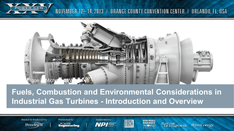
Brian M Igoe & Michael J Welch
Fuels, Combustion and Environmental Considerations in
Industrial Gas Turbines - Introduction and Overview
Restricted © Siemens AG 20XX All rights reserved.
siemens.com/answers
AGENDA
Fuels, Combustion and Emissions
• Introduction
• Environmental Impact
• Combustion Systems
• Fuel Types
Restricted © Siemens AG 2013 All rights reserved.
Page 2
2013-Nov
BMI / MJW SITL
AGENDA
Fuels, Combustion and Emissions
• Introduction
• Environmental Impact
• Combustion Systems
• Fuel Types
Restricted © Siemens AG 2013 All rights reserved.
Page 3
2013-Nov
BMI / MJW SITL
Introduction
Industry requires Energy
• Electricity
• Mechanical Power
• Heat
• Most commonly provided through the combustion of fossil fuels
• Number of technologies can be used
• Gas Turbines
• Boiler / Steam Turbines
• Reciprocating Engines
For this Symposium subjects covered include Fuels and Emissions issues surrounding Gas Turbines
Restricted © Siemens AG 2013 All rights reserved.
Page 4
2013-Nov
BMI / MJW SITL
Fluids / Gases
Turbine Entry / Exit
Some of the fluids entering or exiting the gas turbine core or
package
Exhaust Gas
Combustion Air
Compressed Air
Ventilation Air
Lubricating Oil – through
cooler
Gas and Liquid Fuels
Restricted © Siemens AG 2013 All rights reserved.
Page 5
2013-Nov
BMI / MJW SITL
AGENDA
Fuels, Combustion and Emissions
• Introduction
• Environmental Impact
• Combustion Systems
• Fuel Types
Restricted © Siemens AG 2013 All rights reserved.
Page 6
2013-Nov
BMI / MJW SITL
Environmental Impact
Pollutant
Effect
Method of Control
Carbon Dioxide
Greenhouse Gas
Cycle Efficiency
Sulphur Oxides
Acid Rain
Fuel Treatment
Nitrogen Oxides
Ozone Depletion
Smog
Combustion System
Carbon Monoxide
Poisonous
Combustion System
Hydrocarbons
Poisonous
Greenhouse Gas
Combustion system
Smoke
Visible Pollution
Combustion System
Restricted © Siemens AG 2013 All rights reserved.
Page 7
2013-Nov
BMI / MJW SITL
Environmental Impact
DLE - Introduction / Drivers
• Improve the environmental impact
• More stringent environmental limits
• Customer goals and requirements
• Improved operational reliability
• Simple design with simple operating philosophy
required
• Minimal impact of product cost
• Easy to understand
• Easy to maintain
• Wide fuel range coverage
• Part load capable
Restricted © Siemens AG 2013 All rights reserved.
Page 8
2013-Nov
BMI / MJW SITL
NOx Formation
2200
1600
1400
1200
1000
TV2 = 400°C
= 20 ms
NOX real
mixing
NOx [ppm]
T [°C]
1800
PV2 = 16 bar
Combustor GT Diffusion
Combustor GT Lean Pre-mix
2000
Flame temperature
NOX stoichiometric
mixing
800
0
0
0,5
2
Equivalence ratio
1
1
2
0,5
3
0,3
= 1/excess air ratio
Restricted © Siemens AG 2013 All rights reserved.
Page 9
2013-Nov
BMI / MJW SITL
Emission Abatement Options
Emissions Abatement
Dry Low Emissions
Diffusion Flame
SSI
WI
PSI
Wet Injection Methods:
WI = Water Injection
PSI = Primary Steam Injection
SSI = Secondary Steam Injection
Restricted © Siemens AG 2013 All rights reserved.
Page 10
2013-Nov
BMI / MJW SITL
Combustion
1000
NOx Impact
• Diffusion flame
• Produces high combustor primary zone temperatures
• NOx is a function of temperature
• Results in high thermal NOx formation
• Use of wet injection (Water or Steam) directly into the
primary zone
• Lowers combustion temperature
• Reduced NOx formation
NOx Formation Rate [ ppm/ms ]
100
10
1
0 .1
0 .0 1
Diffusion Flame
0 .0 0 1
0 .0 0 0 1
Lean Pre-mix
0 .0 0 0 0 1
0 .0 0 0 0 0 1
1300
1500
1700
1900
2100
2300
2500
F la m e T e m p e r a tu re [ K ]
Flame Temperature as a function of Air/Fuel ratio
Lean burn
Flame
temperature
• Dry Low Emissions
• Lean pre-mixed combustion
• Results in low combustion temperature
• Low NOx formation
• Low NOx across a wide load and ambient range
Diffusion flame reaction
zone temperature
Diffusion flame
Lean Pre-mixed
(DLE/DLN)
Lean
Stoichiometric
Fuel Air Ratio
Rich
Restricted © Siemens AG 2013 All rights reserved.
Page 11
2013-Nov
BMI / MJW SITL
Environmental Aspects
Pollutant
Effect
Method of Control
Carbon Dioxide
Greenhouse gas
Cycle Efficiency
Carbon Monoxide
Poisonous
DLE System
Sulphur Oxides
Acid Rain
Fuel Treatment
Nitrogen Oxides
Ozone Depletion
Smog
Poisonous
Greenhouse gas
Visible pollution
DLE System
Hydrocarbons
Smoke
16750C
DLE System
DLE System
DLE combustion
Emissions level
NOx/CO TRADE-OFF
Optimum
Temperature
Combustion Aspects
Diffusion Flame
Lean Pre-mix
Operability
21750C
Diffusion Flame (Pressure Jet burner)
Reactor temp
Excessive CO Excessive NOx
Restricted © Siemens AG 2013 All rights reserved.
Page 12
2013-Nov
BMI / MJW SITL
Introduction
Fuels, Combustion and Emissions
Introduction
Fuels Types
Combustion Systems
Environmental Impact
Restricted © Siemens AG 2013 All rights reserved.
Page 13
2013-Nov
BMI / MJW SITL
Combustion
Combustion Systems Available
ANNULAR
Used on aero engines
Used on medium and large gas turbines
Tends not to be site serviceable
Requires major engine disassembly
CAN-ANNULAR
Versatile
Can be changed out at site
Does not require engine disassembly
SILO
Used in some medium and large gas turbines
Can be single or dual combustors
DLE Combustion
Conventional
Combustion
Restricted © Siemens AG 2013 All rights reserved.
Page 14
2013-Nov
BMI / MJW SITL
Combustion Arrangements
Reverse Flow
In-Line Flow
Restricted © Siemens AG 2013 All rights reserved.
Page 15
2013-Nov
BMI / MJW SITL
Dry Low Emissions
Gas Fuel Injection/Mixing
Restricted © Siemens AG 2013 All rights reserved.
Page 16
2013-Nov
BMI / MJW SITL
Combustion Properties and “flashback”
Flame speed
Flame speed is determined by the combustion reaction rates and those rates
depend on:
Equivalence ratio
Fuel type
Flow regime (laminar or turbulent)
Flame speed
Flame Speed v Fuel Type
Laminar Flame Speed
If Air flow velocity > Flame speed (SL) Blow off
If Air flow velocity < Flame speed (SL) Flashback
Laminar Flame Stability
Restricted © Siemens AG 2013 All rights reserved.
Page 17
2013-Nov
BMI / MJW SITL
Combustion
Combustion Types
More pilot means greater diffusion flame
Higher emissions and pilot temperature
Less pilot means more premix
Pilot Burner
less NOx but higher dynamics
80
70
Main burner
Pilot Split (%)
60
High Pilot => High Pilot tip temperature
50
40
30
20
10
0
900
Low Pilot => High Combustion
Dynamics – “Instability”
1000
1100
1200
1300
1400
1500
1600
Contr ol Param e te r
Restricted © Siemens AG 2013 All rights reserved.
Page 18
2013-Nov
BMI / MJW SITL
AGENDA
Fuels, Combustion and Emissions
• Introduction
• Environmental Impact
• Combustion Systems
• Fuel Types
Restricted © Siemens AG 2013 All rights reserved.
Page 19
2013-Nov
BMI / MJW SITL
Fuel Type
Various fuel types - Gaseous Fuels
100%
80%
vol %
60%
40%
20%
CO2
N2
CO
H2
C3H8
C2H6
CH4
0%
Restricted © Siemens AG 2013 All rights reserved.
Page 20
2013-Nov
BMI / MJW SITL
Fuel Parameters
- gaseous fuel
Assessment requirements
Fuel Placement
• Fuel composition
• Include contamination
• Supply conditions
Air Placement
• Environmental requirements
Combustion Products
Restricted © Siemens AG 2013 All rights reserved.
Page 21
2013-Nov
BMI / MJW SITL
Evaluation
W ater Vapour
Oxygen
Carbon Dioxide
Carbon Monoxide
Hydrogen
Methane
Ethane
Propane
i-Butane
n-Butane
i-Pentane
n-Pentane
n-Hexane
n-Heptane
n-Octane
n-Nonane
n-Decane
Hydrogen Sulphide
Nitrogen
Ethene
Propene
Total
H2O
O2
CO2
CO
H2
CH4
C2H6
C3H8
i-C4H10
n-C4H10
i-C5H12
n-C5H12
n-C6H14
n-C7H16
n-C8H18
n-C9H20
n-C10H22
H2S
N2
C2H4
C3H6
Density kg/m3 (ISO conditions)
Molecular Mass
0.00
0.00
0.50
0.00
0.00
94.00
3.50
1.20
0.00
0.00
0.00
0.00
0.00
0.00
0.00
0.00
0.00
0.00
0.80
0.00
0.00
100
35065
48468
941
Temperature corrected Wobbe Index kJ/m3
W obbe Index Calculation Temperature °C
46652
2.5
Temperature °C
Pressure bara
Minimum gas supply temperature °C
Maximum gas supply temperature °C
Gas Constant ft lbf/lb K
Gamma
Species
Methane
Ethane
Propane
Carbon Dioxide
Nitrogen
Formulae
CH4
C2H6
C3 H8
CO2
N2
Mol %
94
3.5
1.2
0.5
0.8
Simple things:
Visual Inspection
Anything unusual? Wt%, Mol %, add to 100%, contaminants, …?
INPUT DATA
0.7235
17.11
LCV kJ/m3 (ISO conditions)
LCV kJ/Kg
LCV Btu/scf
Dewpoint
Step 1: Start with a typical natural gas composition
Step 2: Complete an assessment using gas analysis methods
Can see other species that may be present in other fuels
Calculations shown in lower section – OUTPUT, includes:
Lower Calorific (Heating) Value (LCV or LHV)
Wobbe Index (WI)
Dewpoint
Density
< -20
20.0
2.5
120.0
162.47
1.294
OUTPUT DATA
Specific Gravity (ISO conditions)
Restricted © Siemens AG 2013 All rights reserved.
Page 22
2013-Nov
0.591
BMI / MJW SITL
Fuel Assessment
Assessment requirements
Wobbe Index (WI) parameter
LCV
sg
WI
Compares energy input of different gas fuel compositions, and
indicates the inter-changeability of gas fuels
Cv = Net Calorific Value sg = specific gravity
Temperature Corrected Wobbe Index (TCWI)
Gas may be heated e.g. due to dew point
WI
T
WI
15
*
T 15
TT
WI
T
WI
15
*
288
TT
Temp in Kelvin
Restricted © Siemens AG 2013 All rights reserved.
Page 23
2013-Nov
BMI / MJW SITL
Gaseous fuels- Assessment
Restricted © Siemens AG 2013 All rights reserved.
Page 24
2013-Nov
BMI / MJW SITL
Hydrocarbon Dew Point
W ater Vapour
Oxygen
Carbon Dioxide
Carbon Monoxide
Hydrogen
Methane
Ethane
Propane
i-Butane
n-Butane
i-Pentane
n-Pentane
n-Hexane
n-Heptane
n-Octane
n-Nonane
n-Decane
Hydrogen Sulphide
Nitrogen
Ethene
Propene
Total
H2O
O2
CO2
CO
H2
CH4
C2H6
C3H8
i-C4H10
n-C4H10
i-C5H12
n-C5H12
n-C6H14
n-C7H16
n-C8H18
n-C9H20
n-C10H22
H2S
N2
C2H4
C3H6
Density kg/m3 (ISO conditions)
Molecular Mass
0.00
0.00
0.50
0.00
0.00
94.00
3.50
1.20
0.00
0.00
0.00
0.00
0.00
0.00
0.00
0.00
0.00
0.00
0.80
0.00
0.00
100
35065
48468
941
Temperature corrected Wobbe Index kJ/m3
W obbe Index Calculation Temperature °C
46652
2.5
Temperature °C
Pressure bara
Minimum gas supply temperature °C
Maximum gas supply temperature °C
Gas Constant ft lbf/lb K
Gamma
Let us look at the reasons for understanding dew point and the
need to apply a margin of superheat
< -20
20.0
2.5
120.0
162.47
1.294
Specific Gravity (ISO conditions)
Restricted © Siemens AG 2013 All rights reserved.
Page 25
Ensure fuel gas is maintained in vapour phase
Normal to apply superheat margin
0.7235
17.11
LCV kJ/m3 (ISO conditions)
LCV kJ/Kg
LCV Btu/scf
Dewpoint
Importance of DEW Point
2013-Nov
0.591
BMI / MJW SITL
Hydrocarbon Dew Point
In the previous example the dew point for a typical pipeline
gas fuel is very low so a minimum value is applied – this
prevents freezing in the fuel system vent pipework.
Replacing C5 with a representative breakdown:
Parameter
Mol %
I propane
N propane
0.5
0.5
Pentane
0.5
Mol %
Heptane
0.25
Oxygen, O2
Nitrogen, N2
0.37
9.54
Octane
0.12
Nonane
0.06
Carbon Dioxide, CO2
8.00
Decane
0.03
Methane, C1
73.17
Ethane, C2
3.91
Propane, C3
1.91
Butane, C4
1.14
Propane+; C5+
1.96
Take an example where the C5 species is defined as 1.9%+
Parameter
Assume all is C5:
Dew Point
=
2.6OC
Revised dew point
52.5OC
This demonstrates the importance of providing and using the
correct fuel composition.
Incorrect dew point – hence incorrect supply conditions –
results in gas condensate and impact on turbine operation.
Restricted © Siemens AG 2013 All rights reserved.
Page 26
2013-Nov
BMI / MJW SITL
Summary
A brief overview in the use of fuels in a gas turbine
and impact on the environment
Method of assessment and why it is important to
declare as early as possible the full details of the
composition
Combustion systems types and why DLE, DLN
systems dominate new equipment sales
Aspects of Siemens Energy standard combustion
system detailed
THANK YOU FOR YOUR ATTENTION
Restricted © Siemens AG 2013 All rights reserved.
Page 27
2013-Nov
BMI / MJW SITL


