COLUMBIA UNIVERSITY Department of Electrical Engineering EE
advertisement
COLUMBIA UNIVERSITY Department of Electrical Engineering EE
EE4703: Wireless Communications (Spring 2005)
Solution for Homework Assignment No. 3
Problem 1 Rappaport, p. 169, Problem 4.15
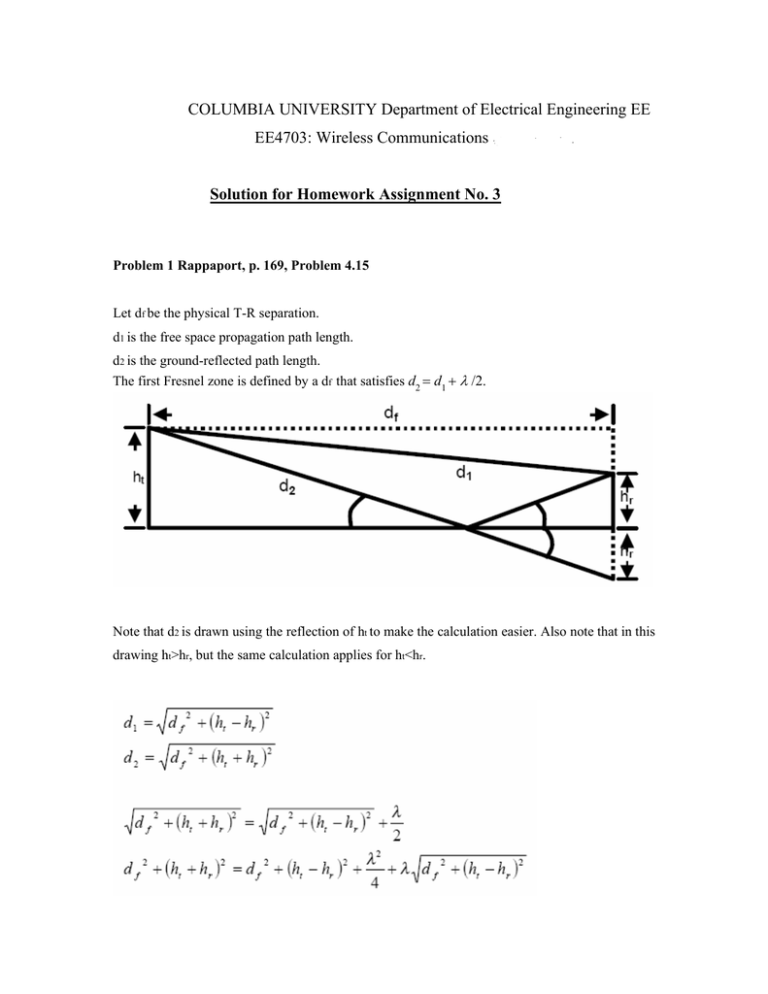
Let df be the physical T-R separation.
d1 is the free space propagation path length.
d2 is the ground-reflected path length.
The first Fresnel zone is defined by a df that satisfies d2 = d1 + λ /2.
Note that d2 is drawn using the reflection of ht to make the calculation easier. Also note that in this
drawing ht>hr, but the same calculation applies for ht<hr.
2 ht h r = −2 ht h r +
d f + (ht − h r )
2
2
1
= 2
λ
λ2
4 ht h r −
4
2
(
)
λ4
16 ht 2 hr 2 − 2 ht h r λ2 + − ht 2 − 2 ht h r + h r 2
16
2
1 λ2
1
λ4
2
2
2
2
2 λ
2
= 2 16 ht hr +
− ht λ2 − hr λ 2 = 2 − 4h t − 4 hr
λ
16
λ 4
4
df2 =
df
2
λ2
2
2
+ λ d f + (ht − h r )
4
df =
1
λ2
(λ
2
− 16 ht
2
)(λ
2
− 16 hr
2
)
4λ
Had we used the parallel ray approximation, we would have received:
S = d 2 − d1 =
df =
2h t hr λ
=
df
2
4ht hr
λ
Which is correct only if the carrier wavelength is very small in comparison with the
receiver and transmitter heights.
_____________________________________________________________________
Problem 2
Rappaport, p. 170, Problem 4.19
Pt = 10 w = 40 dBm
Gt = 10 dB
Gr = 3dB
L = 1dB @ 900 MHz
f = 900 Mhz
∴λ = c
f
1
= m
3
d1
h
hobs
d2
x
y
ht
ht
hr
dt
ht = 60 m
d t = 3000 m
hr = 5m
d r = 2000 m
h obs = 400 m
First, let’s compute the free-space model:
dr
λ2
PL =
= 2.81⋅10−11 = −105.5dB
2
[4π (dt + dr )]
Prec,dBm= Ptr,dBm + PL + Gt ,dB + Gr,dB − LdB = 40 −105.5 + 10 + 3 − 1 = −53.5dBm = 4.47 ⋅10−9 w
We should extract h from the geometry of the problem
d 1 = d t + (h obs − h t ) = 3019 m
2
2
x = arctan(
hobs − ht
) = 6 .47 o
dt
y = arctan(
ht − hr
) = 0.63 o
dt + d r
h = d 1 ⋅ sin( x + y) = 373 .15 m
v = h⋅
2 1 1
+ = 26 .39
λ d 1 d 2
0.225
Gd ,dB = 20 log
= −41 .39 dB
v
And then, the received power is:
Prec = Ptr , dBm + PL + Gt ,dB + G r , dB − L dB + Gd ,dB = − 94 .89 dBm = 3.24 ⋅ 10 −13 w
The received power is 3.24 ·10-13 watts.
Without the obstacle, it would have been 4.47 ·10-9 watts.
The path loss caused by diffraction is 41.39dB.
_____________________________________________________________________
Problem 3
Rappaport, p. 170, Problem 4.20
(a)
f = 50 Mhz
∴ λ = c = 6m
f
λ2
= 9.12 ⋅ 10 −9 = −80 .4 dB
2
[4π (d t + d r )]
PL =
Without diffraction:
P rec, dBm= Ptr , dBm + PL + Gt ,dB + Gr ,dB − LdB = − 28 .4 dBm = 1.45 ⋅10 −6 w
And with diffraction:
= 6 .22
0.225
= 20 log
= − 28 .83 dB
v
v = h⋅
Gd ,dB
2 1
1
+
λ d1 d 2
P rec, dBm= Ptr , dBm + PL + Gt ,dB + Gr ,dB − LdB + G d , dB = −57 .23 dBm = 1.89 ⋅10 −9 w
The received power is 1.89 ·10-9 watts.
Without the obstacle, it would have been 1.45 ·10-6 watts.
The path loss caused by diffraction is 28.83dB.
(b)
f = 1900 Mhz
∴ λ = c = 0 .158 m
f
PL =
λ2
= 6 .24 ⋅10 −12 = −112 .05 dB
2
[4π (d t + dr )]
Without diffraction:
P rec, dBm = Ptr , dBm + PL + Gt ,dB + G r ,dB − L dB = −60 .05 dBm = 9.89 −10 w
And with diffraction:
v = h⋅
2 1
1
+ = 38 .32
λ d1 d 2
0.225
Gd ,dB = 20 log
= − 44 .62 dB
v
P rec, dBm= Ptr , dBm + PL + Gt ,dB + Gr ,dB − LdB + G d , dB = −104 .67 dBm = 3.41 ⋅10 −14 w
The received power is 3.41 ·10-14 watts.
Without the obstacle, it would have been 9.89 ·10-10 watts.
The path loss caused by diffraction is 44.62dB.
_____________________________________________________________________
Problem 4
Rappaport, p. 170, Problem 4.22
P0 = 1mw = 0 dBm
d 0 = 1m
d = 10 m
n = 3.5
We require 10% of the measurements to be stronger than -25dBm.
i.e. Pr{Prec > − 25dBm} = 0.9
We should first find the mean path loss and then look it up in the Q-function table.
d
Prec = P0 − 10 ⋅ n ⋅ log = −35 dB
d0
X −µ
(−35 ) − ( −25)
− 10
Q
= Q
= Q
= 0.9
σ
σ
σ
10
10
Q = 0.1 →
= 1.28
σ
σ
σ = 7 .81dB
The standard deviation would be 7.81 dB
_____________________________________________________________________
Problem 5
Rappaport, p. 172, Problem 4.27
Ptr = 15 w = 41 .76 dBm
Gt = 12 dB = 15 .84
Gr = 3db = 2
BW r = 30 kHz
Frec = 8 dB
f c = 1800 MHz
∴ λ = 0.167 m
n=4
σ = 8dB
d 0 = 1000 m
We require 20 dB SNR 95% percent of the time
i.e. Pr{SNR > 20dB} = 0.95
What is the maximum T-R separation that will ensure that SNR?
We first compute the noise threshold, and then the required received power.
Thermal noise spectral density at room temperature:
KT = −204 dB
w
w
= 3.98 ⋅ 10 −21
Hz
Hz
So the thermal noise at the receives is
KT ⋅ BWr = 1.194 ⋅10 −16 = −129 .2dBm
And the noise floor is:
Frec + KT ⋅ BWr = −121.2dBm
Regarding the SNR:
20 − SNR
= 0 .95
Pr{SNR > 20 dB} = Q
8
SNR − 20
= 1 − 0.95 = 0.05
Q
8
SNR − 20
= 1.645
8
SNR = 33 .16 dB
The required received power will be:
Prec, min = −121 .2 + 33.16 = −88.04dBm
The Power at d0 :
P0 =
Ptr Gt Gr λ2
= 8.39 ⋅10 −8 w = − 40 .76 dBm
2
(4πd 0 )
d
Prec, min = P0 − 10 n ⋅ log max
d0
∴ d max = d 0 ⋅10
P0 , dBm − Prec, min
10 n
= 15 .2 km
_____________________________________________________________________
Problem 6
Rappaport, p. 172, Problem 4.28
SNRreq = 25 dB
f c = 900 MHz
∴ λ = 0 .333 m
EIRP = PtrGt = 100W = 50 dBm
Gr = 0 dB = 1
AMPS → BW = 30 KHz
F = 10 dB
d = 10 km
n=4
σ = 8 dB
d 0 = 1km
We will find P0, and then the average received power.
P0 =
Ptr Gt Gr λ2 EIRP ⋅ Gr λ2
=
= 7.02 ⋅ 10−8 w = −41.54dBm
2
2
(4πd0 )
(4πd0 )
d
Prec = P0 − 10 n ⋅ log
d0
= −81.54dBm
The thermal noise, just like in problem 4.27, is:
KT ⋅ BWr = 1.194 ⋅10 −16 = −129 .2dBm
And the noise floor
NF = Frec + KT ⋅ BWr = −119 .2 dBm
The mean SNR:
SNR = Prec − NF = 37 .66 dB
25 dB − SNR
= Q(− 1 .58 ) = 1 − Q(1 .58 ) = 0.943
Pr{SNR > 25 dB} = Q
σ
The required SNR will be achieved 94.3% of the time.
_____________________________________________________________________

