Gaussian beams w e
advertisement
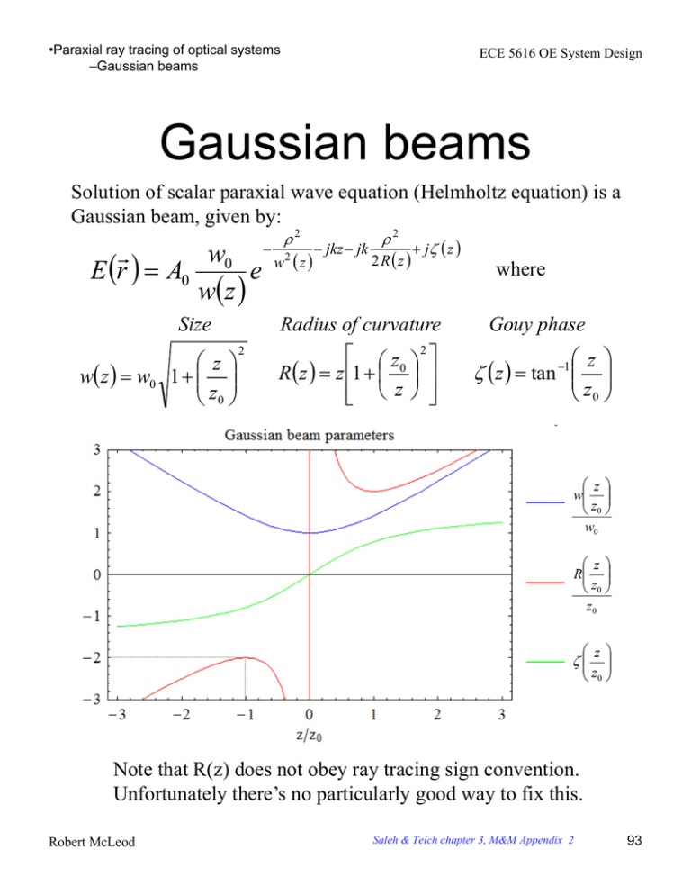
•Paraxial ray tracing of optical systems –Gaussian beams ECE 5616 OE System Design Gaussian beams Solution of scalar paraxial wave equation (Helmholtz equation) is a Gaussian beam, given by: 2 2 w0 w2 z jkz jk 2 R z j z e E r A0 w z Size z w z w0 1 z0 2 where Radius of curvature Gouy phase z0 2 R z z 1 z z z tan z0 1 z w z0 w0 z R z0 z0 z z0 Note that R(z) does not obey ray tracing sign convention. Unfortunately there’s no particularly good way to fix this. Robert McLeod Saleh & Teich chapter 3, M&M Appendix 2 93 •Paraxial ray tracing of optical systems –Gaussian beams ECE 5616 OE System Design Gaussian beams Detailed view Real part of E vs. radius and z w z w z / 2 At z = z0, w z0 2w0 I(0,z0) = I(0,0)/2 R z0 2z0 (min value) Any constant times w(z) is a ray path. Note that the rays are converging and diverging spherical wave except near the focus where they bend. Ergo rays do not always travel in straight lines – the region near the focus violates the slowlyvarying envelope approximation. Conversion formulas w0 1 z0 0 Robert McLeod 0 1 1 w0 z0 z0 2 2 w0 w0 0 0 94 •Paraxial ray tracing of optical systems –Gaussian beams ECE 5616 OE System Design Gaussian beam parameter q(z) The complete Gaussian beam expression normalized to intensity 1 E r A0 w 0 D/2 w0 e w z 2 w2 z jkz jk 2 2Rz D is number of transverse dimensions =1,2 Define the complex radius of curvature 1 1 j qz Rz w2 z What is q(z)? qz j z 1 1 z0 2 z 1 z z j z0 2 2 z z0 z j z0 j 1 z 2 z0 1 z0 argq tan 1 1 z0 z 2 wz 1 z z0 z0 w0 q Can now write Gaussian above as 1 E r j A0 w 0 D/2 z0 e qz jk 2 2qz jkz Note that phase of j/q(z) is Robert McLeod 95 •Paraxial ray tracing of optical systems –Gaussian beams ECE 5616 OE System Design How does q change with transfer and refraction? Free space: Start with expression for q(z) q1 z1 j z0 q2 z 2 j z0 q1 z 2 z1 so q2 = q1 + z Thin lens 1 1 j qz Rz w2 z Start with expression for 1/q(z) 1 1 1 R R f Thin lens equation expressed as change in curvature of wave NOTE HOW GAUSSIAN BEAM SIGN CONVENTION HAS CHANGED THE SIGN 1 1 1 q q f Apply to 1/q q q q f 1 Robert McLeod Solve for q 96 •Paraxial ray tracing of optical systems –Gaussian beams ECE 5616 OE System Design ABCD approach to q Remember the ABCD matrices for thin lens refraction and free-space transfer 1 Rk k 0 1 1 t k Tk 0 1 and define the evolution equation for q Aq B q Cq D Check for free space: 1q t k q q t k 0q 1 Check for thin lens: q q 1q 0 k q 1 q f 1 Which says, rather remarkably, that we can model the propagation of a Gaussian beam through a paraxial optical system using ray matrices. But there’s a better way to do so (at least I like it’s better). Robert McLeod 97 •Paraxial ray tracing of optical systems –Gaussian beams ECE 5616 OE System Design Representation of Gaussian beams by complex rays (1) Define the following three rays. Note their suggestive names and relationship to the Gaussian beam. Paraxial ray trajectory form z w0 z z 0 w0 0 Chief ray Waist location Waist location f Define the complex ray trajectory z z j z Paraxial image plane Waist ray ABCD vector form w0 0 0 0 0 0 This is Greynolds’ definition and yields the proper form of q. Arnaud’s definition yields q*. You can then show that this ray contains q(z) z y j y d dz u j u Robert McLeod z 0 jw0 0 Ray heights over ray slopes z j z0 q z J. Arnaud, Applied Optics, V24, N4, p. 538, 15 Feb 1985 A. W. Greynolds, SPIE V 560, p. 33, 1985 M&M A2.5 E.g. at z=0 98 •Paraxial ray tracing of optical systems –Gaussian beams ECE 5616 OE System Design Representation of Gaussian beams by complex rays (2) First we note: n y u y u n Lagrange invariant (Nspots=1) By brute for tracing of the rays, we can find the following Gaussian parameters based on the two rays at that point: 0 u2 u2 w z Which gives all other beam parameters y2 z y2 z 1/e field radius at this z We could use these two and the expressions for the Gaussian beam parameters to generate the complete Gaussian, but this would be a bit tedious. A more elegant way is to use the complex ray formalism: z d dz y zu j y zu u ju qz At plane z ≠0 Which, apart from the on-axis phase k0S gives the full Gaussian beam at this plane z. Robert McLeod R. Herloski, S. Marshall, R. Antos, Applied Optics, V22, N8, p 1168, 15 Apr 1983 99 •Paraxial ray tracing of optical systems –Gaussian beams ECE 5616 OE System Design Representation of Gaussian beams by complex rays (3) On-axis examples: 1) = 1 m, w0 = 10 , f = 500 m, 1 f – 1 f system. 2) = 1 m, w0 = 10 , f = 500 m, 2 f – 2 f system. 3) = 1 m, w0 = 10 , f = 500 m, 3 f – 3/2 f system. Notes • In (1), second waist is at Fourier plane, as expected. • In (2), second waist occurs before image plane, as expected. • In (3), as distance to lens increases, waist moves to paraxial image plane Robert McLeod 100 •Paraxial ray tracing of optical systems –Gaussian beams ECE 5616 OE System Design Representation of Gaussian beams by complex rays (5) Off-axis examples: 1) = 1 m, w0 = 10 , f = 500 m, 1 f – 1 f system. 2) = 1 m, w0 = 10 , f = 500 m, 2 f – 2 f system. 3) = 1 m, w0 = 10 , f = 500 m, 3 f – 3/2 f system. Notes • In (1), waist is centered at zero (as expected of Fourier trransform) • In (2), image is at -10 m, expected from magnification M=-1. • This type of problem is not possible with the ABCD formalism. Robert McLeod 101 •Paraxial ray tracing of optical systems –Gaussian beams ECE 5616 OE System Design Do Gaussian beams obey paraxial imaging? (1/3) f=10 w z z M=-1 imaging Object at waist z 2 1 -40 -30 -20 -10 10 20 30 -1 -2 f=10 Real object w z z Image not at waist 2 z Demagnifying imaging 1 -40 -30 -20 -10 10 20 30 -1 -2 Real image Answer: Yes. The image is also a Gaussian E field distribution in amplitude and any point on the object down from the peak by some value, say 1/e for the point w(z), will image to the point on the image down from the peak by the same value. Shown above only for real objects conjugate to real images ( -t ≥ f ). Robert McLeod 102 •Paraxial ray tracing of optical systems –Gaussian beams ECE 5616 OE System Design Do Gaussian beams obey paraxial imaging? (2/3) How about for virtual objects? Virtual object f=10 4 w z z 2 Real image z -40 -30 -20 -10 10 20 30 -2 -4 Answer: Still works. Robert McLeod 103 •Paraxial ray tracing of optical systems –Gaussian beams ECE 5616 OE System Design Do Gaussian beams obey paraxial imaging? (3/3) How about for virtual images? 7.5 f=10 5 w z z Virtual image 2.5 z -40 -30 -20 -10 Real object 10 20 30 -2.5 -5 -7.5 Conclusion: All parts of the object Gaussian image correctly to the appropriate parts of the image Gaussian including both real and virtual objects and images. Corollary: If you apply paraxial imaging to the object Gaussian over all z, you generate the image Gaussian over all z. Gaussian beams obey paraxial imaging exactly. Robert McLeod 104 •Design of ideal imaging systems with geometrical optics –Gaussian beam propagation ECE 5616 OE System Design Design example Collimator lens z0 d 2L M T L R T d 1 L q L ABCD from start to center L d 1 L 1 d L d 1 L jz0 1 L 1 d j z0 z02 d 1 d ReqL 0 L 2 2 z0 1 d 2 qL j Robert McLeod z0 j z0 NEW 2 2 2 z0 1 d q at center starting with q = j z0 Where is waist? What is new Rayleigh range? 105
