Sludge Survey Methods for Anaerobic Lagoons
advertisement
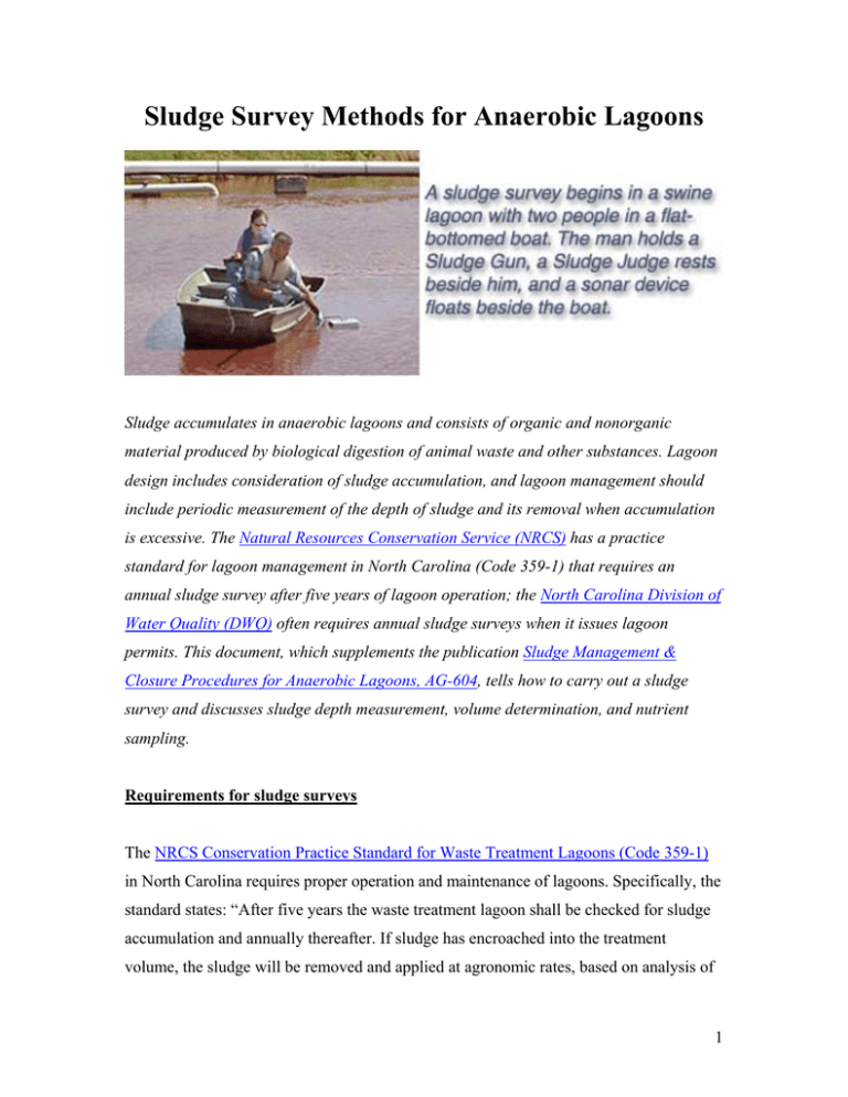
Sludge Survey Methods for Anaerobic Lagoons Sludge accumulates in anaerobic lagoons and consists of organic and nonorganic material produced by biological digestion of animal waste and other substances. Lagoon design includes consideration of sludge accumulation, and lagoon management should include periodic measurement of the depth of sludge and its removal when accumulation is excessive. The Natural Resources Conservation Service (NRCS) has a practice standard for lagoon management in North Carolina (Code 359-1) that requires an annual sludge survey after five years of lagoon operation; the North Carolina Division of Water Quality (DWQ) often requires annual sludge surveys when it issues lagoon permits. This document, which supplements the publication Sludge Management & Closure Procedures for Anaerobic Lagoons, AG-604, tells how to carry out a sludge survey and discusses sludge depth measurement, volume determination, and nutrient sampling. Requirements for sludge surveys The NRCS Conservation Practice Standard for Waste Treatment Lagoons (Code 359-1) in North Carolina requires proper operation and maintenance of lagoons. Specifically, the standard states: “After five years the waste treatment lagoon shall be checked for sludge accumulation and annually thereafter. If sludge has encroached into the treatment volume, the sludge will be removed and applied at agronomic rates, based on analysis of 1 the sludge. Treatment volume must have a minimum of 4 feet of depth free of sludge at all times.” Many permits for animal facilities issued by DWQ require a survey of sludge accumulation in lagoons within one year of receiving the individual permit or Certificate of Coverage (COC) and every year thereafter. The survey frequency may be reduced if it can be demonstrated to the satisfaction of DWQ that the rate of sludge accumulation does not warrant an annual survey. The survey shall include, but not be limited to, a sketch showing the depth of sludge in various locations within each lagoon. If the sludge accumulation is such that it is greater than the sludge volume for which the lagoon was designed or if the accumulation reduces the lagoon’s minimum treatment volume to less than the volume for which the lagoon was designed, a plan must be submitted to the DWQ Central Office within ninety (90) days of the determination, and the plan must document sludge-removal methods and waste-utilization procedures to be used. Sludge characteristics Two distinctly different zones are found within an anaerobic lagoon. First is the sludge accumulation zone at the bottom of the lagoon (Figure 1, “Sludge Accumulation”). The sludge is composed of settled manure solids, nonorganic constituents of manure, active and dead microbial cells, and other materials (debris, sand, etc.) that entered the manure collection system and settled to the bottom. Sludge is black, moderately viscous, 2 Figure 1. An anaerobic waste treatment lagoon (drawing is not to scale). (Adapted from AG-604) typically about 10 percent solids and 90 percent liquid, and high in nutrients, bacteria, and organic matter. Biological anaerobic degradation activity occurs in the sludge, as can be evidenced by the biogas that periodically floats sludge to the liquid surface. Sludge can be handled by pumps designed for higher solids applications, i.e., 10 to 15 percent solids. Refer to Sludge Management & Closure Procedures for Anaerobic Lagoons, AG604, for sludge-removal options. The second distinct zone in the lagoon is the liquid layer above the sludge (Figure 1). This liquid, typically called lagoon supernatant or effluent, is low in solids (generally 0.3 to 0.6 percent solids), moderately rich in nutrients, and easily pumped with irrigation pumps. If the liquid and sludge are mixed, the solids content probably will be between 2 percent and 8 percent solids, depending on the proportion of sludge. Conducting a sludge survey A sludge survey involves locating the top of the sludge layer and measuring its thickness at a number of locations in a lagoon. Both are discussed in “Steps in the sludge survey” 3 and “Measuring sludge layer thickness.” Using the measurements and Appendix1, determine the thickness of the sludge layer and the thickness of the Permanent Liquid Treatment Zone (distance from the Minimum Liquid Level [Figure 1] to the top of the sludge layer). Appendix 2 is a Sludge Survey Data Sheet for recording measurements at each point of the survey grid. The volume of sludge can be estimated, using Appendix 3. Appendix 4 is a conversion table from feet and inches to feet in tenths. If it is anticipated that sludge removal may soon occur, samples of the sludge or “cores” of the liquid column and sludge may be taken at the same time as the survey and sent for nutrient analyses. Unless “remote” methods are developed, the sludge survey and sampling must be conducted from a boat on the lagoon. Special care should be taken when going onto a lagoon in a boat. For safety reasons, at least three people should be present: two in the boat and one on the lagoon bank. The extra person(s) on shore may be needed as a rescuer(s), should anything go awry. The extra person on the boat assists with getting in and out of the boat and anchoring the boat at the measurement locations. Also, it is more efficient if one person in the boat uses the measuring instruments and the other person records the data. Flat-bottom or johnboats are preferred over canoes or V-bottom boats, as they are more stable. All persons working within the inner slopes of the lagoon, and especially those in the boat, should wear appropriate flotation devices. The sludge layer is generally a “mobile” fluid, but it may form peaks and valleys within the lagoon. Small (usually older) lagoons seem to have more variation in sludge layer thickness. For this reason, at least 8 depth measurements should be taken for a lagoon of less than 1.33 acres in area, and at least 6 measurements per acre should be taken for lagoons that are equal to or greater than 1.33 acres, up to a maximum of 24 for the whole lagoon. The locations for measurements should be determined by a uniform grid, if possible. Avoid measuring over the slope of the lagoon embankments. For example, if a lagoon is 12 feet deep and the side slope is 3:1 (horizontal to vertical), then the slope extends for 36 feet into the lagoon. In this case, the measurements should be taken more than 36 feet from the inside top of the lagoon embankment. All measurements from the 4 various locations on the grid should be averaged to produce an average sludge layer thickness and to calculate the volume of sludge. Steps in the sludge survey 1. Gather the necessary equipment (boat, life jackets, paddles, anchor, map or sketch of lagoon, clipboard and pencils, sludge detection device (such as an infrared sensor or a disk-on-rope with interval markings [See “Measuring sludge layer thickness”]) to determine the top of the sludge layer, and a solid rod or pole with interval markings to determine the depth to the lagoon bottom. A 12-foot johnboat with a trolling motor is recommended. There should be two people in the boat and one on the bank. 2. Determine the number of points at which to take measurements. Measure sludge at a minimum of 6 points per acre on a uniform grid, using 24 points maximum, or measure a minimum of 8 points if the lagoon is smaller than 1.33 acres. If you are unsure of the lagoon area, multiply the length times the width at the inside top of the bank and divide by 43,560 to get acres (1 acre = 43,560 ft2). Multiply the number of acres by 6, and round to the nearest number that gives a uniform grid, with minimum of 8 points for lagoons of less than 1.33 acres. Once the number of measurement points has been determined, set up a uniform grid on the lagoon sketch to show the location of those points. For a one-acre lagoon twice as long as it is wide, 8 locations of about 60 feet by 50 feet would be marked on the grid (Figure 2). This sketch must be attached to the “Sludge Survey Data Sheet.” 3. Use survey flags or landmarks (inlet pipe, power pole, confinement house, etc.) on the lagoon bank to mark lines corresponding to the grid developed in item 2. 5 Figure 2. Layout for a lagoon 150 feet x 300 feet (1.03 acres), showing 8 locations to take sludge measurements (4 x 2 grid). 4. Prepare data sheets and forms to record information (use “Lagoon Sludge Survey Form” [Appendix 1] and “Sludge Survey Data Sheet” [Appendix 2] for recording information). 5. Launch boat and move to first sample point. Measure the depth from the surface of the liquid to the top of the sludge. Record this depth. Insert a pole vertically at the same location until the lagoon bottom (soil contact) is felt. Record this depth. The sludge thickness is the difference between the 2 readings. If measurements are taken in feet/inches, convert to feet/tenths using the conversion table in Appendix 4. 6. Proceed to all other sample points and record measurements as in item 5. 7. To determine the average sludge layer thickness in the lagoon, add all sludge layer thickness determinations and divide by the number of readings taken. This average sludge layer thickness will be used in the “Sludge Volume Worksheet” (Appendix 3) to determine how much sludge is in the lagoon, if it is rectangular and has uniform side slopes. If the lagoon has an irregular shape, the sludge volume can be estimated by first estimating the total surface area in square feet and taking the square root to obtain the dimensions for a square lagoon; then you 6 may use the procedures in Appendix 3. If help is needed in determining the total surface area for an irregular shape, contact the local NRCS office. 8. For each survey, the Present Liquid Level should be referenced to a permanent elevation or benchmark, and the Maximum Liquid Level should be noted from the lagoon gauge. Then, by knowing or measuring the difference in elevation between the Maximum Liquid Level and the Minimum Liquid Level on the lagoon gauges, the difference between the Minimum Liquid Level and the top of the sludge layer can be calculated. This is considered the Permanent Liquid Treatment Zone. This should be a minimum of 4 feet in depth, based on NRCS standards. For example, if the total depth from liquid surface to bottom is 8 feet, the liquid level is 1 foot above the Minimum Liquid Level on the lagoon plan or lagoon gauge, and the sludge layer surface is 5.5 feet below the liquid surface (or 2.5 feet sludge layer thickness), then the depth of the Permanent Treatment Zone is 5.5 feet – 1 foot = 4.5 feet (or 8 feet – 1 foot – 2.5 feet = 4.5 feet). (This should be calculated and recorded on the “Lagoon Sludge Survey Form,” Appendix 1.) Measuring sludge layer thickness Basic approach—Measure the depth from the liquid surface to the top of the sludge layer, and then measure the depth from the liquid surface to the lagoon bottom (soil contact); calculate the difference to obtain the thickness of the sludge layer. Depth to top of the sludge—Various methods can be used to measure the depth from the liquid surface to the top of the sludge layer. Although some publications have recommended a capped pipe or a pipe with a disk or a tee attached to the bottom to detect the sludge layer by “feel” (resistance from the sludge), these “feel” methods are likely to yield variable and inaccurate results. Although sludge is more viscous than the lagoon liquid, it is still difficult to feel when the sludge is first encountered. Therefore, feel methods are not recommended. Alternative methods that have proven to be better include commercially available infrared sensors, disk-on-rope, and clear plastic pipe (such as the 7 Sludge Judge) for obtaining a liquid column. Yet another method that may be adequate is an electronic sonar depth finder. Infrared sensors—Depth from the liquid surface to the top of the sludge layer can be measured reliably in most lagoons with infrared detectors (Markland Engineering Sludge Gun1or Raven Sludge Detector2). The infrared detectors indicate when the sludge layer is reached by emitting an audible sound (Sludge Gun) or by “peaking” on the meter dial (Sludge Detector). Because of the audible sound from the Sludge Gun, it is easier to use than the Sludge Detector. The sensitivity of the detectors can be adjusted, but in lagoons with a high solids content, the detectors might “alarm” as soon as the sensor is put into the liquid. If this occurs, another method may be needed to detect the top of the sludge layer. Infrared detectors cost between $400 and $900. Disk-on-rope—A much less expensive but somewhat more time-consuming method to determine the top of the sludge layer is with a disk or plate that sinks through the liquid and settles on the sludge layer. When used carefully, this method generally agrees within 1 inch with the infrared detectors. A PVC disk ¼ inch thick and about 8 to 12 inches in diameter or of square shape (specific gravity = 1.4) has shown results consistent with the infrared detectors. The size (area) of the disk should make little difference because the pressure exerted on the sludge is constant per unit area. Disks of Lexan (s.g. = 1.2) give similar results. Materials that are heavier than PVC may exert more pressure and may penetrate the sludge. The wire, rope, or string by which the infrared detectors or disks are lowered into the lagoon should be marked in inches or tenths of feet for easy reading. This line should not be elastic because stretching will cause variations in readings. The disk should be lowered slowly to keep it from swaying off vertical line. Holes drilled in the disk to allow liquid to pass through may reduce swaying. The rope or string can be attached to the disk at the center or at 2 to 4 symmetrically placed locations to keep the disk more stable. The depth to the sludge layer should be measured with the disk first before using a pole to measure depth to the lagoon bottom because the pole may disturb the sludge layer. 8 Sludge Judge3 or clear plastic pipe—Another method that is considered slightly less accurate for determining the top of the sludge layer is a Sludge Judge or similar clear plastic pipe with a valve at the bottom. If used carefully, this method can agree within 1 to 3 inches with the infrared and disk methods. Typically, however, the sludge does not flow freely into the pipe, and the reading indicates slightly less depth to the sludge than is actually present. Observe the liquid level inside the pipe as the Sludge Judge is slowly lowered into the lagoon. When the sludge layer is reached, the liquid level inside the pipe will drop slightly below the liquid level outside the pipe. Then, the Sludge Judge can be removed and the depth of the liquid column to the sludge can be recorded. (There will be at least 1 to 2 inches of sludge at the bottom end of the pipe to ensure that the sludge layer has been reached). The Sludge Judge costs $60 to $90 and can be ordered in either ¾ inch or 1¼ inch outside diameter. For a self-made apparatus, a ball valve with handle (operated by a rope) can be attached at the bottom of a clear plastic pipe. The pipe can be constructed of sections that can be disassembled for transport. The pipe can be larger, such as 2 inches in diameter, but it will be heavy to handle when collecting liquid and sludge. Experience shows that penetrating the sludge layer with an open pipe does not yield accurate thickness estimates of the sludge layer, probably because of sludge compression or clogging of the pipe. Either the Sludge Judge or a self-made pipe can be used to obtain a sludge sample for nutrient analysis. Electronic sonar depth finder4—Another way to measure sludge layer depth is the depth finder that boaters and fishermen use. A scenario of the future suggests a sensor floating on the lagoon (making it unnecessary for anyone to get on the lagoon in a boat) and a GPS connection to record locations. Investigations with one depth finder and two cone angle transducers attached to a float beside a boat have been conducted with promising results, but more investigation and verification are needed before specific recommendations can be made about unit specifications. 9 Fish finders and depth finders, which utilize sonar (Sound, Navigation, and Ranging) technology, transmit a high-frequency signal from an antenna (called a transducer) and measure the time it takes the signal to be reflected back to the transducer. The receiver then calculates the distance based on the time lapse between the transmitted and reflected signals and the speed at which the signal travels in water (approximately 4,800 feet per second). An experienced operator can obtain good results with a properly selected sonar unit. A suitable unit costs between $120 and $200, but if additional features are desired, the cost may be considerably more. Some of the important considerations for selecting a sonar unit are: • Transmitter power—Higher power increases the likelihood that a signal will be reflected back to the transducer in lagoons with high solids content. • Transducer—Narrow cone angles concentrate the signal in a smaller area and are preferable. • Receiver—Manually adjustable controls, such as sensitivity, are important to reduce false readings, especially in lagoons with high solids content. • Display—A graphic (picture) display with high resolution and good contrast is less likely to produce false readings than a digital display. Measurement considerations: • The relative location of the transducer to the surface of the lagoon liquid should be recorded and the liquid level in the lagoon referenced to a fixed elevation (such as the start/stop pumping marker). 10 • A permanent grid should be determined, and the lagoon bottom elevation should be measured with a pole or other method and recorded for each point on the grid. • The sonar transducer is best mounted on a float independent of the boat so that it remains at a constant location relative to the liquid surface (i.e., it doesn't move up and down with a rocking boat). The distance from the transducer to the liquid surface should be recorded and added to the depth measurement, if necessary. • The sensitivity should be adjusted to the lowest possible setting, and the fish identification feature, if the unit has one, should be turned off to reduce interference from suspended solids. • A measurement should be taken at each reference point. Depth to the bottom of the lagoon—After the depth to the sludge layer has been measured, determine the depth from the liquid surface to the lagoon bottom at the same location. Use a ½-inch to 1-inch diameter pole marked off in inches or tenths of feet. It can be made of wood, aluminum, or PVC with end cap. Push the pole through the sludge until the bottom (soil) is reached. The pole should be held vertically and not be pushed into the soil, only making contact. The marked readings should begin at zero at the end inserted into the lagoon, so that the distance from the lagoon bottom to the liquid surface can be read directly. Poles may be constructed of sections that can be joined together, such as 4-feet lengths of PVC with joints, but the sections should always be assembled so that the depth indicators are accurate. Taking a sludge sample Samples of sludge or “cores” of the lagoon liquid and the sludge may be extracted for laboratory analysis of nutrient content either at the time of the lagoon survey or when it is determined sludge should be removed. Samples should be taken from several locations, then mixed into one composite sample. 11 How the sample is collected depends on how the sludge will be removed. If the lagoon will be agitated to mix lagoon liquid and sludge during sludge removal, a “core” of the mixed liquid and sludge should be taken. A Sludge Judge with a clear plastic tube and “float valve” at the bottom is a useful device for this task. Also, a 1.5-inch diameter PVC pipe with a ball valve at the bottom and a handle operated by a rope can be used to take a core. However, the large-diameter pipe is difficult to manage because the pipe must be longer than the lagoon depth (liquid surface to lagoon soil bottom) and typically will be more than 10 feet long and heavy. Constructing a pipe of 4-foot to 5-foot sections will make the device easier to transport between lagoons and to store. To obtain a liquid/sludge sample, open the valve and slowly insert the pipe vertically into the lagoon until it reaches the bottom. Then pull the rope to close the valve. Pull the pipe up out of the lagoon. This will capture a core or profile of lagoon effluent and sludge. Empty the contents of the pipe into a clean 5-gallon bucket by opening the ball valve. Place several samples in the bucket and mix thoroughly before removing a sub-sample for analysis. A wide-mouthed plastic bottle is a good container for shipping samples to the laboratory. If the lagoon liquid is going to be drawn down and primarily only sludge pumped out, then only the sludge portion of the core of liquid and sludge should be released into the bucket and sampled. Another method of obtaining a sludge sample is with a “grab sampler,” such as the Ekman Bottom Grab Sampler 5. If you are unsure how the sludge will be removed, take a sample of sludge only and a sample of the sludge/liquid entire core, label them separately, and have both analyzed. For more information on preparing samples for analysis, consult Sludge Management & Closure Procedures for Anaerobic Lagoons (AG-604); Chapter 3, “Tools for the Plan,” 12 Certification Training Manual for Operators of Animal Waste Management Systems (AG-538); or Soil Facts: Waste Analysis (AG-439-33) . Notes 1 Sludge Gun Model 10 from Markland Specialty Engineering Ltd. of Toronto, Canada, has a price, including shipment, of $875; it includes a 10-meter cable marked in feet. Phone (416) 2444980; email: markland@sludgecontrols.com; or online at www.sludgecontrols.com. It makes an audible sound when the sludge layer is detected. 2 Raven Sludge Detector by Raven Environmental Products can be ordered from USA BlueBook (item # 41424). Phone 1-800-548-1234. Price about $450. The meter dial pointer “peaks” when sludge layer is detected. 3 Sludge Judge information can be found online at www.pollardwater.com (3 types with prices of about $60 to $90 for a 15-foot length in three 5-foot sections); phone 1-800-437-1146; or at Wildlife Supply Co., www.wildco.com (1 type with price of about $70 for 15-foot length); phone 1800-799-8301. 4 The electronic sonar depth finder method should be used only by individuals who have experience with equipment set-up and operation. In addition, the operation of any equipment should be verified under lagoon conditions before actually being used on a boat in a lagoon. 5 The Ekman Bottom Grab Sampler is available from various sources, such as Wildlife Supply Co., online at www.wildco.com; phone 1-800-799-8301. 13 Appendix 1. Lagoon Sludge Survey Form A. Farm Permit or DWQ Identification Number______________________________________ B. Lagoon Identification ___________________________________________________ C. Person(s) Taking Measurements ___________________________________________ D. Date of Measurements __________________________________________________ E. Methods/Devices Used for Measurement of: a. Distance from the lagoon liquid surface to the top of the sludge layer: __________________________________________________________________ b. Distance from the lagoon liquid surface to the bottom (soil) of the lagoon: __________________________________________________________________ c. Thickness of the sludge layer if making a direct measurement with “core sampler”: __________________________________________________________________ F. Lagoon Surface Area (using dimensions at inside top of bank): _____________(acres) (Draw a sketch of the lagoon on a separate sheet, list dimensions, and calculate surface area.) G. Estimate number of sampling points: a. Less than 1.33 acres: Use 8 points b. If more than 1.33 acres, ______ acres x 6 = _______, with maximum of 24. (Using sketch and dimensions, develop a uniform grid that has the same number of intersections as the estimated number of sampling points needed. Number the intersection points on the lagoon grid so that data recorded at each can be easily matched.) H. Conduct sludge survey and record data on “Sludge Survey Data Sheet” (Appendix 2). I. At the time of the sludge survey, also measure the distance from the Maximum Liquid Level to the Present Liquid Level (measure at the lagoon gauge pole): ______ J. Determine the distance from the Maximum Liquid Level to the Minimum Liquid Level (use lagoon management plan or other lagoon records): ______ K. Calculate the distance from the present liquid surface level to the Minimum Liquid Level ______ (Item J minus Item I, assuming the present liquid level is below the Maximum Liquid Level): L. Record from the Sludge Survey Data Sheet the distance from the present liquid surface level to the lagoon bottom (average for all the measurement points): ______ M. Record from the Sludge Survey Data Sheet the distance from the present liquid surface level to the top of the sludge layer (average for all the measurement points): ______ N. Record from the Sludge Survey Data Sheet the average thickness of the sludge layer: ______ O. Calculate the thickness of the existing Liquid Treatment Zone (Item M minus Item K): ______ (Note: If Item O is less than 4 feet, a sludge removal and utilization plan may be required by N.C. DWQ. See your specific permit or contact DWQ for more information.) P. Proceed to the Sludge Volume Worksheet if you desire to calculate sludge volume for a rectangularshaped lagoon with uniform side slopes. Completed by: _______________________ ____________________________ Date: _____________ Print Name Signature 14 Appendix 2. Sludge Survey Data Sheet* Lagoon Identification: ___________________________________ Sludge Survey Data Sheet Completed by: ___________________ _______________________ Date:_____________ Print Name (A) (B) Grid Point No. Distance from liquid surface to top of sludge Ft. & in. Ft. (tenths) Signature (C) (C) minus (B) Distance from liquid surface Thickness of sludge to lagoon bottom (soil) layer Ft. & in. Ft. (tenths) Ft. & in. Ft. (tenths) 1 2 3 4 5 6 7 8 9 10 11 12 13 14 15 16 17 18 19 20 21 22 23 24 Average *All Grid Points and corresponding sludge layer thicknesses must be shown on a sketch attached to this Sludge Survey Data Sheet. See Appendix 4 for conversion from inches to tenths of a foot. 15 Appendix 3. Sludge Volume Worksheet. The average thickness of the sludge layer is determined from information on the Lagoon Sludge Survey Form. In this example, the average sludge layer thickness is 2.5 feet. The dimensions of the lagoon and the side slope are needed for calculations. If the lagoon is a standard geometric shape, the volume of sludge in the lagoon can then be estimated by using standard equations. For rectangular lagoons and constant side slope, calculate length and width at the midpoint of the sludge layer, and multiply by sludge layer thickness to calculate sludge layer volume, as shown in the example. For irregular shapes, convert the total surface area to a square shape. Example Your lagoon A. Average Sludge Layer Thickness (T) 2.5 ft. ____________ B. Depth of lagoon from top of bank to bottom soil surface (D) 11 ft. ____________ C. Slope = horizontal/vertical side slope (S) 3 ____________ D. Length at top inside bank (L) 457 ft. ____________ E. Width at top inside bank (W) 229 ft. ____________ F. Length at midpoint of sludge layer Lm = L – 2 S (D- (T/2)) 398.5 ft. ____________ G. Width at midpoint of sludge layer Wm = W – 2 S (D – (T/2)) 170.5 ft. ____________ H. Volume of sludge (V) V = Lm Wm T 169,860 ft3 ____________ I. Volume in gallons Vg =V * 7.5 gal./ft3. 1,273,950 gal. ____________ 16 Appendix 4. Conversion table from inches to tenths of a foot. Inches Tenths of foot 1 0.1 2 0.2 3 0.2 4 0.3 5 0.4 6 0.5 Inches 7 8 9 10 11 Tenths of foot 0.6 0.7 0.7 0.8 0.9 17 Prepared by Philip W. Westerman, Professor, Department of Biological and Agricultural Engineering, North Carolina State University Karl A. Shaffer, Extension Associate, Department of Soil Science, North Carolina State University J. Mark Rice, Extension Specialist, Department of Biological and Agricultural Engineering, North Carolina State University This publication is intended to supplement Sludge Management & Closure Procedures for Anaerobic Lagoons, AG-604, prepared by Ronald E. Sheffield, James C. Barker, and Karl A. Shaffer (May 2000). The focus of this publication is on sludge survey methods and reporting. Some of the material in this publication is adapted from AG-604. The use of trade or brand names in this publication does not imply endorsement of products mentioned or criticism of similar products not mentioned. Copyright © 2003 by North Carolina State University Published by North Carolina Cooperative Extension Service Distributed in furtherance of the acts of Congress of May 8 and June 30, 1914. North Carolina State University and North Carolina A&T State University commit themselves to positive action to secure equal opportunity regardless of race, color, creed, national origin, religion, sex, age, or disability. In addition, the two Universities welcome all persons without regard to sexual orientation. North Carolina State University, North Carolina A&T State University, U.S. Department of Agriculture, and local governments cooperating. 8/03—JL E04-43933 AGW-639 18
