Lecture-09
advertisement
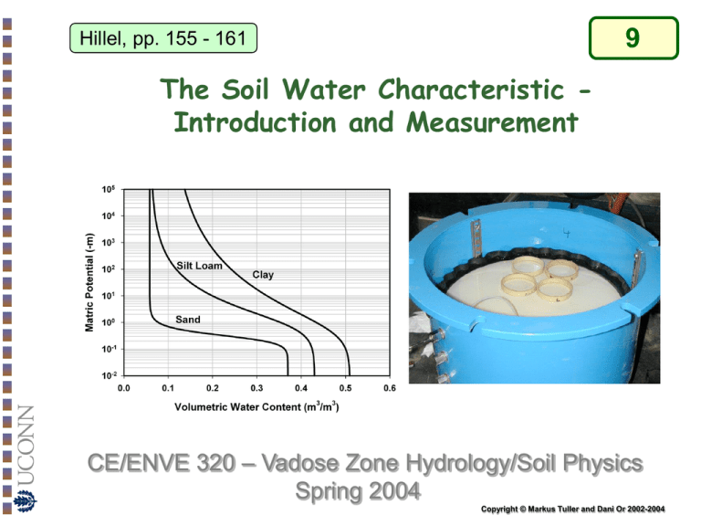
9 Hillel, pp. 155 - 161 The Soil Water Characteristic Introduction and Measurement CE/ENVE 320 – Vadose Zone Hydrology/Soil Physics Spring 2004 Copyright © Markus Tuller and Dani Or 2002-2004 The Soil Water Characteristic Curve ● The Soil Water Characteristic (SWC) curve describes the functional relationships between soil water content (qv or qm) and matric potential under equilibrium conditions. ● The SWC is an important soil property related to pore space distribution (sizes, interconnectedness), which is strongly affected by texture and structure and related factors including organic matter. ● The SWC is a primary hydraulic property required for modeling water flow in porous materials. ● The SWC function is highly nonlinear and relatively difficult to obtain accurately. Copyright© Markus Tuller and Dani Or2002-2004 The Soil Water Characteristic Curve Typical soil water characteristic curves for soils of different texture Copyright© Markus Tuller and Dani Or2002-2004 The Soil Water Characteristic Curve Early conceptual models for SWC curve were based on the "bundle of cylindrical capillaries" (BCC) representation of pore space geometry (Millington and Quirk, 1961). The BCC representation postulates that at a given matric potential a portion of interconnected cylindrical pores is completely liquid filled, whereas larger pores are completely empty. Soil sample actual pore equivalent capillary Copyright© Markus Tuller and Dani Or2002-2004 The Soil Water Characteristic Curve This convenient idealization of soil pore space enables a linkage between the soil pore size distribution and the SWC based on capillary rise equation 2 cos hi w g r i Ai ri ni 2 Copyright© Markus Tuller and Dani Or2002-2004 BCC Model - Example A bundle of cylindrical capillaries having the following diameters and numbers was vertically dipped into a water reservoir. # of capillaries 300 Diameter [mm] 0.001 400 325 250 150 90 50 10 5 2 0.005 0.01 0.02 0.05 0.1 0.2 0.5 1 2 Compute and plot the relative saturation of the capillaries at different elevations above the free water surface : The first step is to calculate the capillary rise for various capillary diameters: h 2 cos w gr For each elevation we then calculate the cross-sectional area of all filled capillaries: 2 d A n 4 We start with the highest elevation where only capillaries with the smallest diameter are likely to be filled. Then we gradually move down to the lowest elevation where all capillaries are expected to be filled. At each elevation increment we add the water filled cross-sectional areas of capillaries with smaller diameters. Copyright© Markus Tuller and Dani Or2002-2004 BCC Model - Example Finally we calculate the relative saturation at each elevation as the ratio of water-filled cross-sectional area at a certain elevation and the total crosssectional area. # Diameter [m] h [m] A 2 [m ] 300 1E-06 29.74 2.36E-10 0.000016 400 5E-06 5.95 8.09E-09 0.000544 325 1E-05 2.97 3.36E-08 0.002262 250 2E-05 1.49 1.12E-07 0.007548 150 5E-05 0.59 4.07E-07 0.027371 90 1E-04 0.30 1.11E-06 0.074945 50 2E-04 0.15 2.68E-06 0.180666 10 5E-04 0.06 4.65E-06 0.312817 5 1E-03 0.03 8.58E-06 0.577118 2 2E-03 0.01 1.49E-05 1.000000 qvrel Copyright© Markus Tuller and Dani Or2002-2004 BCC Model - Example Characteristic Curve of a Bundle of Cylindrical Capillaries Elevation above free water [m] 30 20 10 0 0.000 0.001 0.002 0.008 0.027 0.075 0.181 0.313 0.577 1.000 Relative saturation of the capillaries Copyright© Markus Tuller and Dani Or2002-2004 Using SWC to determine pore size distribution 1) The total saturation water contend qs is divided into a certain number M of equal increments Dqv where the matric potential hj corresponds to a water content of qs- jxDqv 2) We assume that all tubes with radii greater than Rj have drained at matric potential hj 2 rRj w g h j Copyright© Markus Tuller and Dani Or2002-2004 Using SWC to determine pore size distribution 3) The number of capillaries having a radius Rj per unit area in each water content interval is: nj=Dqv/Rj2 (where Dqv is interpreted as the fraction of the water-filled cross sectional area that is reduced when all capillaries having a radius of Rj drain). Frequency - ft,r - (m-1 ) 0.020 0.015 0.010 0.005 0.000 0 20 40 60 Pore Radius - r - (m) 80 Copyright© Markus Tuller and Dani Or2002-2004 SWC and Plant Available Soil Revisited • The concept of Field Capacity and Wilting Point discussed in the previous section on water content have a more quantitative definition in terms of potentials and SWC. • Field Capacity - water content @ 1/3 bar (for sandy soils 0.1 bar) • Wilting Point – water content @ -15 bars Copyright© Markus Tuller and Dani Or2002-2004 Measurement Methods for SWC The basic requirement is to find pairs of water content q and matric potential ym over the wetness range of interest. Experimental Difficulties: •The limited functional range (-10 m) of tensiometers used for in-situ measurements. •Difficulty to obtain undisturbed samples for laboratory determination. •Very long equilibration times for low matric potential values associated with dry soils Copyright© Markus Tuller and Dani Or2002-2004 Tempe Cell The pressure flow cell (Tempe cell) is usually applied for the pressure (matric potential) range from 0 to -10 m. Gas Pressure Brass Ring Soil Sample Outflow Ceramic Plate Close to saturation soil water retention is strongly influenced by soil structure and the natural pore size distribution. Therefore undisturbed core samples are preferred over repacked samples. Copyright© Markus Tuller and Dani Or2002-2004 Pressure Plate Apparatus The pressure plate apparatus is applied for the pressure (matric potential) range from -10 to -50 m. Porous Plate with Samples Soil Sample Chamber Pressure Atmospheric Pressure Porous Plate Copyright© Markus Tuller and Dani Or2002-2004 Pressure Plate Apparatus Copyright© Markus Tuller and Dani Or2002-2004 Hanging water column and suction table Measurements at very low pressure ranges of 0 to 2 m. Useful for coarse soils due to precise pressure application. Wetting and drying cycles of the SWC (reversible flow into the sample). Dh Copyright© Markus Tuller and Dani Or2002-2004 Vapor Pressure-Based Methods A procedure inferring water potential using thermocouple psychrometers that is commonly used in newer instruments is called DEWPOINT METHOD In this method one surface is brought to dew point temperature and kept at exactly this temperature using a monitoring system and electronic circuitry. State of the art equipment (e.g., WP4 Potentiameter) uses chilled mirror dewpoint technique combined with a photoelectric detection system to keep the surface of a mirror at dewpoint temperature. Ambient temperature at the sample surface is measured with an infrared thermometer. WP4 Potentiameter Copyright© Markus Tuller and Dani Or2002-2004 In-situ measurement methods – Sensor Pairing SENSOR PAIRING: (TDR, Neutron Probe, Tensiometer, Heat Dissipation, etc) Example - TDR Probes installed in close proximity to transducer-equipped tensiometers are commonly used for automated recording of changes of water content and matric potential with time. IN-SITU MEASUREMENTS ARE CONSIDERED MOST REPRESENTATIVE. Copyright© Markus Tuller and Dani Or2002-2004 Field Measurement Methods - Sensor Pairing Limitations: • Differences in the soil volumes sampled by each sensor, e.g. large volume averaging by a neutron probe vs. a small volume sensed by heat dissipation sensor or psychrometer • In-situ water content measurement methods are instantaneous, matric potential sensors require time for equilibrium; hence the two measurements may not be indicative of the same wetness level • Limited ranges and deteriorating accuracy of different sensor pairs; this often results in limited overlap in retention information and problems with measurement errors within the range of overlap. Copyright© Markus Tuller and Dani Or2002-2004 SWC measurement ranges Copyright© Markus Tuller and Dani Or2002-2004 Hillel, pp. 155 - 161 The Soil Water Characteristic Parametric Models and Hysteresis CE/ENVE 320 – Vadose Zone Hydrology/Soil Physics Spring 2004 Copyright © Markus Tuller and Dani Or 2002-2004 Parametric SWC Models Measuring a SWC is laborious and time consuming. Usually there are only a few data pairs available from measurements. For modeling and analysis (characterization and comparison of different soils) it is beneficial to represent the SWC relationship as continues parametric function. Commonly used parametric models are the van Genuchten and Brooks & Corey relationships. q .... Water Content at Saturation s Van Genuchten Model (1980): q qr 1 n q s q r 1 y m m qr .... Residual Water Content ym... Matric Potential ..... Shape Parameter m .... Shape Parameter n ..... Shape Parameter 1 m 1 n The unknown parameters (free parameters) , n, and qr can be obtained by fitting the model to a few (at least 5-8) measured data pairs (Nonlinear regression with 0 ≤ m ≤ 1, and qr 0). Copyright© Markus Tuller and Dani Or2002-2004 Parametric SWC Models Brooks and Corey Model (1964): q qr y b q s q r y m 1 l ym yb ym yb qs .... Water Content at Saturation qr .... Residual Water Content ym... Matric Potential yb ... Bubbling Pressure (Air Entry Value) l ..... Parameter Related to the Shape of the Pore Size Distribution The unknown parameters (free parameters) yb, qr,and l can be obtained by fitting the model to measured data pairs In both models MATRIC POTENTIALS are expressed as positive (absolute) quantities. There are various computer codes available (e.g., RETC) for estimation of free model parameters. A simple procedure is the application of solver tools that are part of most spreadsheet software packages. Copyright© Markus Tuller and Dani Or2002-2004 Van Genuchten and Brooks & Corey Models Copyright© Markus Tuller and Dani Or2002-2004 Fitting SWC models Copyright© Markus Tuller and Dani Or2002-2004 Typical “van Genuchten” Model Parameters Table1: Typical van Genuchten model parameters (, n) including residual (qr) and saturated (qs) water contents compiled from the UNSODA database (Leij et al., 1996). N indicates the number of soils or samples of a given textural class from which the mean values are compiled. N qr 3 [cm /cm3] qs 3 [cm /cm3] [1/cm] n Sand 126 0.058 0.37 0.035 3.19 Loamy Sand 51 0.074 0.39 0.035 2.39 Sandy Loam 78 0.067 0.37 0.021 1.61 Loam 61 0.083 0.46 0.025 1.31 Silt 3 0.123 0.48 0.006 1.53 Silt Loam 101 0.061 0.43 0.012 1.39 Sandy Clay Loam 37 0.086 0.40 0.033 1.49 Clay Loam 23 0.129 0.47 0.030 1.37 Silty Clay Loam 20 0.098 0.55 0.027 1.41 Silty Clay 12 0.163 0.47 0.023 1.39 Clay 25 0.102 0.51 0.021 1.20 Textural Class Copyright© Markus Tuller and Dani Or2002-2004 Databases for Soil Hydraulic Properties Table 1-1: Textural Averages of Hydraulic Parameters Based on UNSODA Unsaturated Hydraulic Properties Database and NRCS Soil Survey Database (Leij, et al., 1999). Saturated Hydraulic conductivity Water Retention Textural Class † N † qr qr [1/cm] n N 0.035 0.035 0.021 0.025 0.006 0.012 3.19 2.39 1.61 1.31 1.53 1.39 74 31 50 31 2 62 505.8 226.5 41.6 38.3 55.7 30.5 † Ks [cm/d] Sand Loamy Sand Sandy Loam Loam Silt Silt Loam Sandy Clay Loam Clay Loam Silty Clay Loam Silty Clay Clay 126 51 78 61 3 101 0.058 0.074 0.067 0.083 0.123 0.061 UNSODA 0.37 0.39 0.37 0.46 0.48 0.43 37 0.086 0.40 0.033 1.49 19 9.69 23 20 12 25 0.129 0.098 0.163 0.102 0.47 0.55 0.47 0.51 0.030 0.027 0.023 0.021 1.37 1.41 1.39 1.20 8 10 6 23 1.84 7.41 8.40 26.0 Sand Loamy Sand Sandy Loam Loam Silt Silt Loam Sandy Clay Loam Clay Loam Silty Clay Loam Sandy Clay Silty Clay Clay 246 315 1183 735 82 1093 0.045 0.057 0.065 0.078 0.034 0.067 SOIL SURVEY 0.43 0.41 0.41 0.43 0.46 0.45 0.145 0.124 0.075 0.036 0.016 0.020 2.68 2.28 1.89 1.56 1.37 1.41 246 315 1183 735 88 1093 712.18 350.2 106.1 25.0 60.0 10.8 214 0.100 0.39 0.059 1.48 214 31.4 364 641 46 374 400 0.095 0.089 0.100 0.070 0.068 0.41 0.43 0.38 0.36 0.38 0.019 0.010 0.027 0.005 0.008 1.31 1.23 1.23 1.09 1.09 345 592 46 126 114 6.24 1.68 2.88 0.48 4.80 Databases for hydraulic soil properties have been compiled by several agencies. These data are good estimates for various soil textural classes and may be used as initial guesses for optimization of measured data. Approximate sample size for Soil Survey database Copyright© Markus Tuller and Dani Or2002-2004 Databases for Soil Hydraulic Properties Graphical representation of various SWC curves contained in the UNSODA and NRCS databases. 10 a 8 9 7 6 Soil Survey 1 Sand 7 Sandy clay loam 2 Loamy sand 8 Clay loam 3 Sandy loam 9 Silty clay loam 4 Loam 11 Silty clay 5 Silt 12 Clay 6 Silt loam 11 5 8 6 7 3 4 4 4 8 3 9 11 2 2 12 1 1 2 2 0 0 0.0 1 Sand 7 Sandy clay loam 2 Loamy sand 8 Clay loam 3 Sandy loam 9 Silty clay loam 4 Loam 10 Sandy clay 5 Silt 11 Silty clay 6 Silt loam 12 Clay 5 6 log h (cm) log h (cm) 8 6 10 UNSODA 12 4 0.1 0.2 q 0.3 0.4 0.5 0.0 b 0.1 0.2 0.3 0.4 0.5 q Copyright© Markus Tuller and Dani Or2002-2004 Hysteretic behavior of SWC Soil Water Content and Matric Potential are not uniquely related and depend on the path of saturation or desaturation. SWC can be either obtained by desaturation of an initially saturated sample by applying suction or pressure (DRYING CURVE), or by gradually wetting of an initially oven-dry sample (WETTING CURVE). The two procedures often produce different SWC curves the water content of the drying branch is typically higher than water content of a wetting curve at the same potential. This phenomenon is known as HYSTERESIS Copyright© Markus Tuller and Dani Or2002-2004 Hysteresis in SWC The Hysteresis in the SWC relationship depends on several micro- and meso-scale phenomenon: “INK BOTTLE” EFFECT resulting from non-uniformity in shape and size of interconnected pores: Drainage is governed by the smaller pore radius, whereas wetting is governed by the larger radius. (Large pores drain first but fill up last) Different LIQUID-SOLID CONTACT ANGLES for advancing and receding liquid. ENTRAPPED AIR in newly wetted soil SWELLING AND SHRINKING of soil under wetting and drying (a) r (b) R Gas 1 hd hW Liq So lid uid 2 The role of individual factors remains unclear and is subject of ongoing research. Copyright© Markus Tuller and Dani Or2002-2004 Hysteresis in SWC – meso-scale Meso-scale manifestation of hysteresis through Lattice Boltzmann simulation of liquid configuration in complex pore spaces. Entrapment of liquid in pore clusters Copyright© Markus Tuller and Dani Or2002-2004
