MOLD DESIGN
advertisement

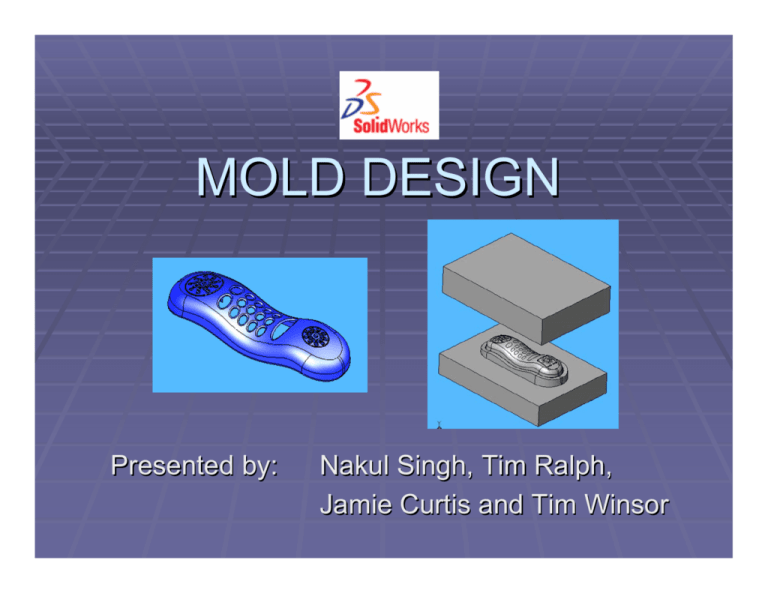
MOLD DESIGN Presented by: Nakul Singh, Tim Ralph, Jamie Curtis and Tim Winsor Mold Design Three main components: (a) Core – This duplicates the inner surface of the model. It is larger than the finished part to allow for material shrinkage during cooling (b) Cavity – This duplicates the outer surface of the model. (c) Mounting bosses – Holds and position core and cavity. Applications • Plastic Injection Molding • Liquid Polymer Molding • Metal Die Casting Boss Positioning • The mounting boss is placed on the selected planar or circular surface. • For direction, select a plane surface. If no selection is made then the boss is placed normal to the surface selected earlier. • A circular edge is selected to position the center axis of mounting boss. Boss Boss Diameter : Sizes the base of the mounting boss. Mating Face : The boss height is set to the meet the selected surface. Base Height : Sets the height of the boss from the base to the mounting hole or pin. Draft Angel : Sets draft for the main boss. Fins Sets direction vector to position the fin Fin height Fin width Fin length – measured from the center of the boss Adds draft to the fin Number of fins Mounting Hole/Pin Either specify the hole/pin diameter or select a mating surface. Reference Plane Plane (Reference Geometry toolbar) Create a plane through an edge, axis or a point. Create a plane through a point parallel to a plane or face. Create a plane perpendicular to a curve. Create a plane on a non-planar surface. Mirroring the Mounting Bosses Mirror ( Feature toolbar) In the Feature Manager select the reference plane and the two mounting bosses that are to be mirrored. Checking the Draft Draft Analysis (Mold Tools toolbar) Draft Analysis tool is used to check the correct application of draft to the faces of the part. It can be used to verify draft angles, locate parting lines, injection and ejection surfaces in parts. Undercut Detection •Identifies areas that require a side core. •When the main core and cavity are separated, the side core slides in a direction perpendicular to the main core and cavity which thus enables the part to be ejected. Undercut Detection Settings for Analysis Direction of Pull All faces are evaluated to determine if they are visible from below the part. This will identify depressions in the wall of the part that require a side core. Parting Line Faces above or below the parting line are evaluated to determine if they are visible from above or below the parting line. This helps identify the need for side cores. Undercut Detection Direction 1 Faces that are not visible from above the part or parting line. Direction 2 Faces that are not visible from below the part or parting line. Occluded Faces that are not visible above or below the part. Straddle Faces that are in both directions. Undercut Detection Example: The cord plug-in hole in this phone is occluded. Therefore, a side core is required after you create the mold. Adding Draft Allows you to add critical draft to mold faces. Set the desired draft angle. Set direction of pull. Scaling Scale Tool Compensates for plastic shrinkage. Scales only the geometry! (Not dimensions, sketches, reference geometry). Select the solid to scale, choose scale size, and select uniform. Parting Lines Choose the parting line. Allows for a draft as well as adds parting lines. Select direction of pull, reverse if necessary. Parting Lines Set draft angle. Note: A system generated parting line does not guarantee that all faces have sufficient draft. Parting Lines Compare colors to check your parting line choice. This color key allows for the user to verify that there are no straddle faces, as well as faces that do not have draft whatsoever. Adding Shut off Surfaces First, click Shut-off Surfaces (Mold toolbar). In the Property Manager, all the holes that go through the surface appear in Edges. Under Edges, select the following: Knit. Joins each shut-off surface into the cavity and core surfaces . Filter loops. Filters out loops that do not appear to be valid holes. Show callouts. Adding Shut off Surfaces Once the steps on the previous slide are completed, an image such as this one will be generated. As you can see under the Property Manager, Knit, Filter Loops and Show callouts are all selected. Beware, this will take a fair bit of time and even the strongest machine in the computer lab will suffer! Loop: Contact are the aforementioned “Call outs”. Adding Shut off Surfaces After clicking the check mark and minutes (or hours) of your computer suffering, an image like this will appear. Creating Parting Surfaces Next, you’ll need to create a Parting Surface (a surface in which the mold will part from). First, click Parting Surfaces (Mold toolbar). Next in the Property Manager, under Mold Parameters, select Perpendicular to pull. Under Parting Surface, set Distance to X mm (10 mm in this case). Under Options, select Knit all surfaces and Show preview. Creating Parting Surfaces Here is what the part will look like in SolidWorks. Following the instructions from the previous slide, select the boxes from and enter the Parting Surface distance. Creating Parting Surfaces After clicking okay, then watching your computer die a little bit, you get this image. Preparing for the Tooling Split To do this, Rotate the surface to the hollow side (bottom) and Zoom in to the rectangular rib above the mouthpiece and select the top face of the rib. Next, Click Plane (Reference Geometry toolbar). Click Front View. In the Property Manager, under Selections, Face<1> appears in Reference Entities : Set Distance to X mm (20 mm in this case). Click okay. Preparing for the Tooling Split After performing the previous slide actions and image such as this should appear. Notice Plane 10? Remember it, you’ll need to use it for Tool Splitting. Applying the Tooling Split Next, a Tool Split needs to be added. To do this, click Tooling Split (Mold toolbar). A sketch will open. Click Normal to (Standard Views toolbar). Click Hidden Lines Removed. Click Rectangle and sketch a rectangle and dimension as shown above. Applying the Tooling Split In the Property Manager, make sure that under Core “Shut off Surface1[1] appears. Likewise, assure that under Cavity and Parting Surface “Shut off Surface1[2]” and “Parting Surface1” appear. Next, click Isometric and under Block Size: Set Depth in Direction 1 to X (90mm in this case) Set Depth in Direction 2 to X (70 mm in this case) Select Interlock surface. Applying the Tooling Split The reason the preceding slide was necessary is because this creates your mold box (as can be seen above) By turning on Solid With Edges your mold box is over the piece. Cores Molds from two solid halves restrict the geometrical possibilities for the part. More complicated parts require geometry extraction from a tooling solid by using a core feature. The SolidWorks Core tool is very useful in these situations Example of Constructing a Core Plastic part at right has a recessed feature that requires a core. This requires the creation of a sketch on the tooling solid to define the outline of the core. Then use the Core tool to create the core. Sketch outline of core. Example of Constructing a Core (cont’d) With the sketch selected, click Core Tool on the Mold Tools toolbar, or click Insert, Molds, Core. A new body is created for the core and is subtracted from the Cavity Body. Once the core has been created, an extraction direction needs to set. This can be done by selecting a face on the cavity body. Core for Cell Phone Mold Separating the Core from the Cavity Core, as mentioned earlier, also refers to the half of the mold that fills the interior of the part, usually the bottom of the mold. Cavity refers to the other half of the mold which has a hollow for the part to fit into. Remove the part to see how the Core and Cavity look separately. Use SolidWorks Move/Copy Tool. Moving the Cavity This is a simple step that requires minimal input. First select the body to move. Set a separation distance, delta Y. Enhancing Mold Visibility Enhance the mold visibility by hiding the Solid Bodies and Surface Bodies. To hide the solid body of the phone, under Solid Bodies, right click Parting Line and select Hide Solid Body. To hide the cavity, core and parting surfaces, under Surface Bodies right click each feature and select Hide. Enhancing Mold Visibility Mold visibility can be further improved by editing the colour features. Users can vary the Colour, Transparency, Ambience, Diffusion, Specularity, Shininess and Emissivity levels to improve the appearance of the mold. Creating the Tooling Assembly The separate parts of the molds can be saved and placed together in an assembly file. This requires saving the Core and Cavity as individual parts. First rename the parts under Solid Bodies, Right Click, select Insert into New Part. Creating the Tooling Assembly As with other parts and assemblies in SolidWorks, the Core and the Cavity are very easily inserted into an assembly file and then mated to align with each other. Questions???


