Sensor Data for Navigation
advertisement
Sensor Data for Navigation
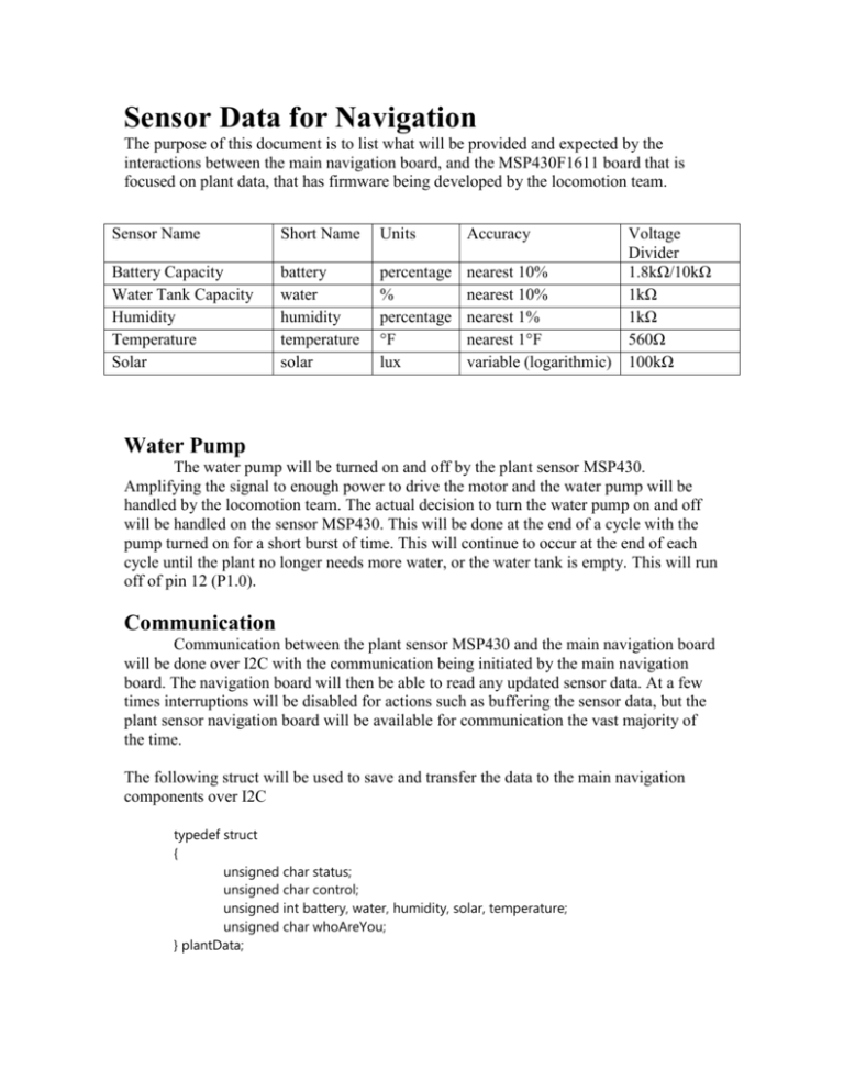
The purpose of this document is to list what will be provided and expected by the
interactions between the main navigation board, and the MSP430F1611 board that is
focused on plant data, that has firmware being developed by the locomotion team.
Sensor Name
Short Name
Units
Accuracy
Battery Capacity
Water Tank Capacity
Humidity
Temperature
Solar
battery
water
humidity
temperature
solar
percentage
%
percentage
°F
lux
nearest 10%
nearest 10%
nearest 1%
nearest 1°F
variable (logarithmic)
Voltage
Divider
1.8kΩ/10kΩ
1kΩ
1kΩ
560Ω
100kΩ
Water Pump
The water pump will be turned on and off by the plant sensor MSP430.
Amplifying the signal to enough power to drive the motor and the water pump will be
handled by the locomotion team. The actual decision to turn the water pump on and off
will be handled on the sensor MSP430. This will be done at the end of a cycle with the
pump turned on for a short burst of time. This will continue to occur at the end of each
cycle until the plant no longer needs more water, or the water tank is empty. This will run
off of pin 12 (P1.0).
Communication
Communication between the plant sensor MSP430 and the main navigation board
will be done over I2C with the communication being initiated by the main navigation
board. The navigation board will then be able to read any updated sensor data. At a few
times interruptions will be disabled for actions such as buffering the sensor data, but the
plant sensor navigation board will be available for communication the vast majority of
the time.
The following struct will be used to save and transfer the data to the main navigation
components over I2C
typedef struct
{
unsigned char status;
unsigned char control;
unsigned int battery, water, humidity, solar, temperature;
unsigned char whoAreYou;
} plantData;
Sensor Details
Battery - Battery Capacity will be provided to the navigation team to the nearest 10%.
The voltage division will be done with a 1.8kΩ resistor and a 10kΩ resistor. This
voltage division will be handled by the locomotion team.
Water Tank - Water Tank Capacity will be provided to the navigation team to
approximately 10%. Voltage division will be done with a 1kΩ resistor, that is set
up by the navigation team. The sensor/ruler will be placed diagonally in order to
fit, and give a higher resolution reading.
Humidity - Humidity will be calculated as a percentage of the humidity in the air. This is
being calculated as a straight linear conversion, and as a result will be given to the
nearest 1%. Voltage division is done by two 1kΩ resistors, and will be handled by
the navigation team.
Temperature - Temperature information will be provided to the navigation team in °F,
to the nearest degree. Temperature information comes from a LM34 sensor that is
provided by the locomotion team. This signal does not need a voltage divider, but
a 560Ω resistor is used to connect the signal to ground. Another 560Ω and a 20kΩ
resistors are placed in parallel leading to the sensor's power pin. Plans to get the
temperature from a digital thermometer are not being used as the MSP430 does
not support the 1-wire communications standard, and lack the internal capacitance
needed to implement it, leaving the microcontroller able to transmit only ones and
not zeros.
Solar measurement - The amount of sun going to the plant will be measured by a photo
resistor. This will be measured in lux. A 100kΩ resistor will be used for voltage
division. The accuracy of this sensor is logarithmic, so the accuracy of the sensor
is a bit variable.
Sensor Schematics
Water Level Sensor
Humidity Sensor
Temperature Sensor
Solar Photo-Resistor


