VMWARE VSPHERE 5 - PART 1: CONFIGURING AND MANAGING
advertisement
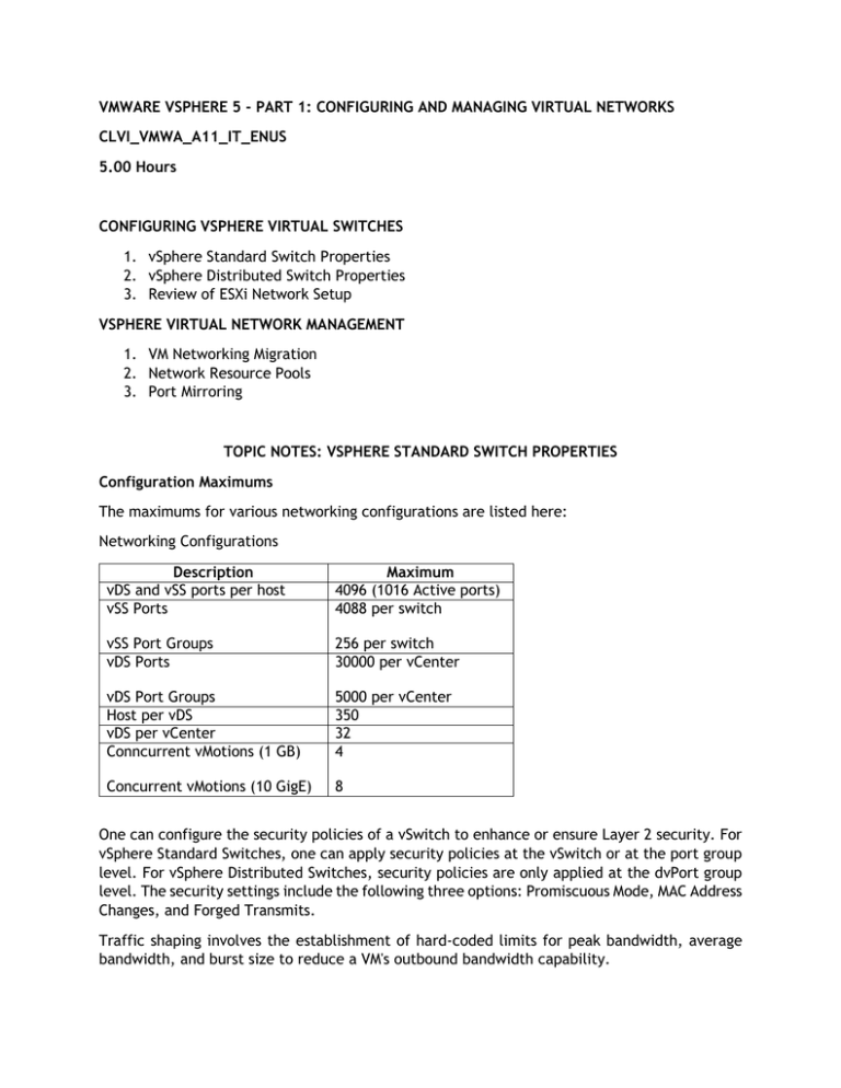
VMWARE VSPHERE 5 - PART 1: CONFIGURING AND MANAGING VIRTUAL NETWORKS CLVI_VMWA_A11_IT_ENUS 5.00 Hours CONFIGURING VSPHERE VIRTUAL SWITCHES 1. vSphere Standard Switch Properties 2. vSphere Distributed Switch Properties 3. Review of ESXi Network Setup VSPHERE VIRTUAL NETWORK MANAGEMENT 1. VM Networking Migration 2. Network Resource Pools 3. Port Mirroring TOPIC NOTES: VSPHERE STANDARD SWITCH PROPERTIES Configuration Maximums The maximums for various networking configurations are listed here: Networking Configurations Description vDS and vSS ports per host vSS Ports Maximum 4096 (1016 Active ports) 4088 per switch vSS Port Groups vDS Ports 256 per switch 30000 per vCenter vDS Port Groups Host per vDS vDS per vCenter Conncurrent vMotions (1 GB) 5000 per vCenter 350 32 4 Concurrent vMotions (10 GigE) 8 One can configure the security policies of a vSwitch to enhance or ensure Layer 2 security. For vSphere Standard Switches, one can apply security policies at the vSwitch or at the port group level. For vSphere Distributed Switches, security policies are only applied at the dvPort group level. The security settings include the following three options: Promiscuous Mode, MAC Address Changes, and Forged Transmits. Traffic shaping involves the establishment of hard-coded limits for peak bandwidth, average bandwidth, and burst size to reduce a VM's outbound bandwidth capability. The vSwitch port-based load-balancing policy that is used by default uses an algorithm that ties (or pins) each virtual switch port to a specific uplink associated with the vSwitch. The algorithm attempts to maintain an equal number of port-to-uplink assignments across all uplinks to achieve load balancing. This policy setting ensures that traffic from a specific virtual network adapter connected to a virtual switch port will consistently use the same physical network adapter. In the event that one of the uplinks fails, the traffic from the failed uplink will failover to another physical network adapter. vSS Port Group Properties When configuring Port Group Properties, a VM network's General Properties include the network label/name and optional vLAN ID for layer 2 vLAN tagging. VMkernel networking carries management traffic, but it also carries all other forms of traffic that originate with the ESXi host itself (that is any traffic that isn't generated by VMs running on that ESXi host). VMkernel ports are used for vMotion, iSCSI, NAS/NFS access, and vSphere FT. With ESXi, VMkernel ports are also used for management. A VMkernel port is associated with an interface and assigned an IP address for accessing iSCSI or NFS storage devices or for performing vMotion with other ESXi hosts. vSS Security Policies Promiscuous Mode option is set to Reject by default to prevent virtual network adapters from observing any of the traffic submitted through the vSwitch. For enhanced security, allowing Promiscuous Mode is not recommended. Despite the security concerns, there are valid reasons for permitting a switch to operate in Promiscuous Mode. An intrusion-detection system (IDS) requires the ability to identify all traffic to scan for anomalies and malicious patterns of traffic. When a VM is created with one or more virtual network adapters, a MAC address is generated for each virtual adapter. Just as Intel, Broadcom, and others manufacture network adapters that include unique MAC address strings, VMware is a network adapter manufacturer that has its own MAC prefix to ensure uniqueness. Of course, VMware doesn't actually manufacture anything because the product exists as a virtual NIC in a VM. All VMs have two MAC addresses: the initial MAC and the effective MAC. The initial MAC is the before mentioned generated MAC. The effective MAC address is the MAC address configured by the guest OS that is used during communication with other systems. The difference between the MAC Address Changes and Forged Transmits security settings involves the direction of the traffic. MAC Address Changes is concerned with the integrity of incoming traffic, while Forged Transmits oversees the integrity of outgoing traffic. If the MAC Address Changes option is set to Reject, traffic will not be passed through the vSwitch to the VM (incoming) if the initial and the effective MAC addresses do not match. If the Forged Transmits option is set to Reject, traffic will not be passed from the VM to the vSwitch (outgoing) if the initial and the effective MAC addresses do not match. vSS Traffic Shaping By default, all virtual network adapters connected to a vSwitch have access to the full amount of bandwidth on the physical network adapter with which the vSwitch is associated. In other words, if a vSwitch is assigned a 1 Gbps network adapter, then each VM configured to use the vSwitch has access to 1 Gbps of bandwidth. Naturally, if contention becomes a bottleneck hindering VM performance, NIC teaming will help. However, as a complement to NIC teaming, it is also possible to enable and to configure traffic shaping. Traffic shaping involves the establishment of hard-coded limits for peak bandwidth, average bandwidth, and burst size to reduce a VM's outbound bandwidth capability. The Peak Bandwidth value and the Average Bandwidth value are specified in kilobits per second, and the Burst Size value is configured in units of kilobytes. The value entered for the Average Bandwidth dictates the data transfer per second across the virtual vSwitch. The Peak Bandwidth value identifies the maximum amount of bandwidth a vSwitch can pass without dropping packets. Finally, the Burst Size value defines the maximum amount of data included in a burst. The burst size is a calculation of bandwidth multiplied by time. During periods of high utilization, if a burst exceeds the configured value, packets are dropped in favor of other traffic; however, if the queue for network traffic processing is not full, the packets are retained for transmission at a later time. vSS NIC Teaming In order for a vSwitch and its associated ports or port groups to communicate with other ESXi hosts or with physical systems, the vSwitch must have at least one uplink. An uplink is a physical network adapter that is bound to the vSwitch and connected to a physical network switch. With the uplink connected to the physical network, there is connectivity for the VMkernel and the VMs connected to that vSwitch. But what happens when that physical network adapter fails, when the cable connecting that uplink to the physical network fails, or the upstream physical switch to which that uplink is connected fails? With a single uplink, network connectivity to the entire vSwitch and all of its ports or port groups is lost. This is where NIC teaming comes in. NIC teaming involves connecting multiple physical network adapters to single vSwitch. NIC teaming provides redundancy and load balancing of network communications to the VMkernel and VMs. After a NIC team is established for a vSwitch, ESXi can then perform load balancing for that vSwitch. The load-balancing algorithm for NIC teams in a vSwitch is a balance of the number of connections — not the amount of traffic. NIC teams on a vSwitch can be configured with one of the following four load-balancing policies: vSwitch port-based load balancing (default), Source MAC-based load balancing, IP hash-based load balancing and explicit failover order. Network Adapters When working in the Network Adapters Tab, one can configure the physical NICs of an ESXi host. The details sections provides the name, location (PCI slot), and driver used by the NIC. The Configuration tab will provide an administrator a status view of any configured NICs within the ESXi host, including speed, the vSwitch to which the NIC is bound to, as well as physical and networking addressing. TOPIC NOTES: VSPHERE DISTRIBUTED SWITCH PROPERTIES vDS Properties The Properties tab of a dvSwitch allows an administrator to view/edit the vDS name and the number of uplinks (physical adapters) to which the dvSwitch will be assigned. The Advanced Tab allows for the configuration of the MTU of the switch, the discovery protocol to be used to obtain protocol addressing, and platform information of neighboring devices – and how that discovery protocol behaves in terms of sharing information about itself to the rest of the network. Previous versions of vSphere supported Cisco Discovery Protocol (CDP), a protocol for exchanging information between network devices. However, it required using the command line to enable and configure CDP. In vSphere 5.0, VMware added support for Link Layer Discovery Protocol (LLDP), an industry-standardized form of CDP, and provided a location within the vSphere Client where CDP/LLDP support can be configured. There is also a field in which to supply administrative contact information. vDS Network Adapters From the Network Adapters tab, and administrator can view the current physical adapter / uplink assignment. Configurations can be made in the Networking section of the Host Configuration tab. vDS Private VLAN Private VLANs (PVLANs) are an advanced networking feature of vSphere that build on the functionality of vSphere Distributed Switches. Private VLANs are possible only when using a vDS and are not available to use with vSphere Standard Switches. PVLANs are a way to further isolate ports within a VLAN. For example, consider the scenario of hosts within a demilitarized zone (DMZ). Hosts within a DMZ rarely need to communicate with each other, but using a VLAN for each host quickly becomes unwieldy for a number of reasons. By using PVLANs, you can isolate hosts from each other while keeping them on the same IP subnet. PVLANs are configured in pairs: the primary VLAN and any secondary VLANs. The primary VLAN is considered the downstream VLAN; that is, traffic to the host travels along the primary VLAN. The secondary VLAN is considered the upstream VLAN; that is, traffic from the host travels along the secondary VLAN. To use PVLANs, first configure the PVLANs on the physical switches connecting to the ESXi hosts, and then add the PVLAN entries to the vDS in vCenter Server. vDS NetFlow NetFlow is a mechanism for efficiently reporting IP-based traffic information as a series of traffic flows. Traffic flows are defined as the combination of source and destination IP address, source and destination TCP or UDP ports, IP, and IP Type of Service (ToS). Network devices that support NetFlow will track and report information on the traffic flows, typically sending this information to a NetFlow collector. Using the data collected, network administrator's gain detailed insight into the types and amount of traffic flows across the network. In vSphere 5.0, VMware introduced support for NetFlow with vSphere Distributed Switches (only on version 5.0.0 dvSwitches). This allows ESXi hosts to gather detailed per-flow information and report that information to a NetFlow collector. vDS Port Mirroring Port Mirroring capability can assist and administrator when monitoring or troubleshooting issues in a virtual infrastructure. Once configured with a destination (network monitoring device, VM, VMkernel, Uplink), the vDS can send copies of packets being sent out a dvSwitch port to the destination device. dvUplink Settings Many of these settings have been previously discussed. However, there are certain policies and properties and functionality only available to a vDS. Ingress and Egress Traffic shaping allows an administrator control over the traffic shaping configurations for traffic going from the virtual switch to the virtual NIC and traffic going from the virtual NIC to the virtual switch, respectively. VLAN settings allow an administrator to configure a port group for a VLAN (and VLAN ID settings) or to act as a VLAN trunk. Additional settings allow one to include the port group in a Network Resource Pool, close all ports on the dvUplink, and override port policies and configurations. TOPIC NOTES: REVIEW OF ESXI NETWORK SETUP ESXi Setup Revisited Additionally, many virtual networking settings can be configured via the DCUI. DNS and Routing The Configuration tab of the selected ESXi host will allow an administrator to configure DNS and Routing configurations for the host. Within the Properties screen, the host name, domain, DNS server specifications, and routing (default gateway) can be configured. Enable IPv6 If implemented in the virtual environment, IPv6 can be enabled for the selected ESXi host. Network Adapters The Configuration tab of a selected ESXi host will display any installed/available physical NICS, as well as their associated speed, vSwitch associations, MAC address, and observed IP ranges. TOPIC NOTES: VIRTUAL MACHINE MIGRATION Migrating Virtual Machine Networking With a vDS, managing adapters — both virtual and physical — is handled quite differently than with a standard vSwitch. Virtual adapters are VMkernel interfaces, so by managing virtual adapters, we're really talking about managing VMkernel traffic — management, vMotion, IPbased storage, and Fault Tolerance logging — on a dvSwitch. Physical adapters are, of course, the physical network adapters that serve as uplinks for the dvSwitch. Managing physical adapters means adding or removing physical adapters connected to ports in the dvUplinks dvPort group on the dvSwitch. After a VM network is migrated, it will reconfigure all selected VMs to use the selected destination network. This is a lot easier than individually reconfiguring a bunch of VMs! In addition, this tool allows you to easily migrate VMs both to a vDS as well as from a vDS. TOPIC NOTES: NETWORK RESOURCE POOLS Creating a Network Resource Pool A network resource pool allows one to control network utilization. Using network resource pools — to which are assigned shares and limits — one can control outgoing network traffic. This feature is referred to as vSphere Network I/O Control (NetIOC). Once vSphere NetIOC is enabled, vSphere activates six predefined network resource pools: Fault Tolerance (FT) Traffic, iSCSI Traffic, Management Traffic, NFS Traffic, Virtual Machine Traffic, and vMotion Traffic. Additionally, in vSphere 5, Host Based Replication Traffic (HBR) is also available. Assigning a dvPortGroup to a Network Resource Pool The general steps for assigning a dvPortGroup to a Network Resource Pool are listed here: 1. 2. 3. 4. Manage Port Groups Assign dvPort Group dvPort is assigned Select NRP and view Details TOPIC NOTES: PORT MIRRORING Port Mirroring Port Mirroring can be configured to allow a vSwitch to send a copy of any packets on a particular vSwitch port to another vSwitch port, or network monitoring device. This can assist with troubleshooting. Useful Networking Tabs When working with a vSwitch, keep in mind the following tabs and the types of information displayed on each. Useful Networking Tabs Summary Network Ports Resource Allocation Configuration dvSwitch x x x x x dvUplinks x dvPort Groups x x x
