Constant Acceleration Physics Unit: Worksheets & Labs
advertisement

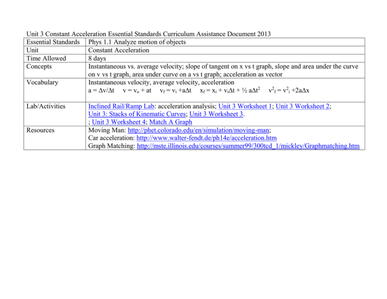
Unit 3 Constant Acceleration Essential Standards Curriculum Assistance Document 2013 Essential Standards Phys 1.1 Analyze motion of objects Unit Constant Acceleration Time Allowed 8 days Concepts Instantaneous vs. average velocity; slope of tangent on x vs t graph, slope and area under the curve on v vs t graph, area under curve on a vs t graph; acceleration as vector Vocabulary Instantaneous velocity, average velocity, acceleration a = ∆v/∆t v = vo + at vf = vi +a∆t xf = xi + vi∆t + ½ a∆t2 v2f = v2i +2a∆x Lab/Activities Resources Inclined Rail/Ramp Lab: acceleration analysis; Unit 3 Worksheet 1; Unit 3 Worksheet 2; Unit 3: Stacks of Kinematic Curves; Unit 3 Worksheet 3. ; Unit 3 Worksheet 4; Match A Graph Moving Man: http://phet.colorado.edu/en/simulation/moving-man; Car acceleration: http://www.walter-fendt.de/ph14e/acceleration.htm Graph Matching: http://mste.illinois.edu/courses/summer99/300tcd_1/mickley/Graphmatching.htm Lab Notes: Inclined Rail Motion Apparatus High Tech. Pasco dynamics carts and tracks or large steel ball photogates (2) Computer and ULI interface ULI Timer (software for Macintosh) Graphical Analysis Low Tech. Bowling ball, chalk and accessibility ramp or disc and axle and parallel-pipe ramp Stopwatch, water clock, metronome or pendulum Ticker tape, masking tape and markers Graphical Analysis Pre-lab discussion • • • • • Let a ball roll down an inclined rail and ask students for observations. Record all observations. To proceed, they must mention something to the effect that the ball speeds up as it rolls down. To obtain a finer description, ask students which observations are measurable. Make sure they include the observation that the ball speeds up as it rolls down the rail. (Do not let them state the ball accelerates since we haven't defined acceleration yet!) Ask them how they can measure speed directly. Lead them to the conclusion that they cannot, but that they can measure position and time. Students should mark the position of the object at equal time intervals. Time should be plotted as the independent variable. Lab performance notes • • Position Position • • A variety of constant acceleration motion such as a cart rolling down a track, a bowling ball rolling down an access ramp, or a disc and axle rolling down a ramp of two parallel pieces of conduit pipe. Timing variations could include using photogates, water clocks, pendulums and metronomes in addition to stopwatches. Make sure that the angle of inclination is less than 30o. Initial position and speed must be zero. (See sample graphs below.) Time ©Modeling Workshop Project 2006 Time2 2 Unit III ws 1 v3.0 UNIT III: Worksheet 1 When evaluating problems 1 - 3, please represent the motion that would result from the rail configuration indicated by means of a: A) qualitative graphical representation of x vs. t E) general mathematical expression of the B) qualitative graphical representation of v vs. t relationship between x and t C) qualitative graphical representation of a vs. t F) general mathematical expression of the D) qualitative motion map relationship between v and t G) general mathematical expression of the relationship between a and t x D) x t E) _____________________________ v t F) ____________________________ a t G)____________________________ ©Modeling Workshop Project 2006 3 Unit III ws 1 v3.0 2) x D) x t E) _____________________________ v t F) ____________________________ a G)____________________________ t ©Modeling Workshop Project 2006 4 Unit III ws 1 v3.0 Name Date Pd UNIT III: Worksheet 2 While cruising along a dark stretch of highway with the cruise control set at 25 m/s (≈55 mph), you see, at the fringes of your headlights, that a bridge has been washed out. You apply the brakes and come to a stop in 4.0s. Assume the clock starts the instant you hit the brakes. 1. Construct a motion map that represents the motion described above, including position, velocity, and acceleration. Clearly demonstrate how you can determine the direction (sign) of the acceleration from the motion map representation. 2. Construct qualitative graphical representations of the situation described above to illustrate: a. x vs. t b. v vs. t c. a vs. t ©Modeling Workshop Project 2006 5 Unit III ws 1 v3.0 3. Construct a quantitatively accurate v vs t graph to describe the situation. 4. On the v vs t graph at right, graphically represent the car’s displacement during braking. 5. Utilizing the graphical representation, determine how far the car traveled during braking. (Please explain your problem solving method.) 6. In order to draw the a vs t graph, you need to determine the car’s acceleration. Please do this, then sketch a quantitatively accurate a vs t graph 7. Using the equation you developed for displacement of an accelerating object determine how far the car traveled during braking. (Please show your work.) 8. Compare your answers to 5 and 7. ©Modeling Workshop Project 2006 6 Unit III ws 1 v3.0 Unit III: Stacks of kinematics curves Given the following position vs time graphs, sketch the corresponding velocity vs time and acceleration vs time graphs. ©Modeling Workshop Project 2006 7 Unit III ws 1 v3.0 For the following velocity vs time graphs, draw the corresponding position vs time and acceleration vs time graphs. ©Modeling Workshop Project 2006 8 Unit III ws 1 v3.0 Name Date UNIT III: Worksheet 3 1. x (m) 25 0 5 t (s) a. Describe in words the motion of the object from 0 - 6.0 s. b. Construct a qualitative motion map to describe the motion of the object depicted in the graph above. c. What is the instantaneous velocity of the object at the following times? i. t = 1.0 s ii. t = 3.0 s d. What is the simple average of these two velocities? What is the average velocity for the entire interval? Why are these two values different? Which is best to describe the motion of the object? ©Modeling Workshop Project 2006 9 Unit III ws 1 v3.0 Pd v (m/s) e. Graphically represent the relationship between velocity and time for the object described above. 0 t (s) 5 f. From your velocity vs. time graph determine the total displacement of the object. 2. The graph below represents the motion of an object. x B C A t D E G F a. At what point(s) on the graph above is the object moving most slowly? (How do you know?) b. Over what intervals on the graph above is the object speeding up? (How do you know?) c. Over what intervals on the graph above is the object slowing down? (How do you know?) d. At what point(s) on the graph above is the object changing direction? (How do you know?) ©Modeling Workshop Project 2006 10 Unit III ws 1 v3.0 3. A stunt car driver testing the use of air bags drives a car at a constant speed of 25 m/s for a total of 100. m. He applies his brakes and accelerates uniformly to a stop just as he reaches a wall 50. m away. a. Sketch qualitative position vs. time and velocity vs time graphs. b. How long does it take for the car to travel the first 100.m? c. Remember that the area under a velocity vs time graph equals the displacement of the car. How long must the brakes be applied for the car to come to a stop in 50 m? d. Now that you know the total time of travel, sketch a quantitative velocity vs time graph. e. What acceleration is provided by the brakes? How do you know? ©Modeling Workshop Project 2006 11 Unit III ws 1 v3.0 Name Date Pd UNIT III: Worksheet 4 + v (m/s) 1. A poorly tuned Geo Metro can accelerate from rest to a speed of 28 m/s in 20 s. a) What is the average acceleration of the car? b) What distance does it travel in this time? t (s) - + v (m/s) 2. At t = 0 a car has a speed of 30 m/s. At t = 6 s, its speed is 14 m/s. What is its average acceleration during this time interval? t (s) - 3. A bear spies some honey and takes off from rest, accelerating at a rate of 2.0 m/s2. If the honey is 16 m away, how fast will his snout be going when it reaches the treat? v (m/s) + 4. A bus moving at 20 m/s (t = 0) slows at a rate of 4 m/s each second. a) How long does it take the bus to stop? b) How far does it travel while braking? t (s) - v (m/s) + t (s) - ©Modeling Workshop Project 2006 12 Unit III ws 1 v3.0 v (m/s) 5. A physics student skis down a hill, accelerating at a constant 2.0 m/s2. + If it takes her 15 s to reach the bottom, what is the length of the slope? t (s) - v (m/s) 6. A dog runs down his driveway with an initial speed of 5 m/s for 8 s, then uniformly increases his speed to + 10 m/s in 5 s. a) What was his acceleration during the 2nd part of the motion? b) How long is the driveway? t (s) - v (m/s) 7. A mountain goat starts a rock slide and the rocks crash down the slope 100 m. If the rocks reach the bottom in 5 s, what is their acceleration? + t (s) - v (m/s) 8. A car whose initial speed is 30 m/s slows uniformly to 10 m/s in 5 seconds. a) Determine the acceleration of the car. b) Determine the distance it travels in the 3rd second + (t = 2s to t = 3s). t (s) - ©Modeling Workshop Project 2006 13 Unit III ws 1 v3.0 Graph Matching One of the most effective methods of describing motion is to plot graphs of position, velocity, and acceleration vs. time. From such a graphical representation, it is possible to determine in what direction an object is going, how fast it is moving, how far it traveled, and whether it is speeding up or slowing down. In this experiment, you will use a Motion Detector to determine this information by plotting a real time graph of your motion as you move across the classroom. The Motion Detector measures the time it takes for a high frequency sound pulse to travel from the detector to an object and back. Using this round-trip time and the speed of sound, you can determine the position to the object. Logger Pro will perform this calculation for you. It can then use the change in position to calculate the object’s velocity and acceleration. All of this information can be displayed either as a table or a graph. A qualitative analysis of the graphs of your motion will help you develop an understanding of the concepts of kinematics. walk back and forth in front of Motion Detector OBJECTIVES Analyze the motion of a student walking across the room. Predict, sketch, and test position vs. time kinematics graphs. Predict, sketch, and test velocity vs. time kinematics graphs. MATERIALS computer Vernier computer interface Logger Pro Vernier Motion Detector meter stick masking tape PRELIMINARY QUESTIONS 1. Use a coordinate system with the origin at far left and positive positions increasing to the right. Sketch the position vs. time graph for each of the following situations: An object at rest An object moving in the positive direction with a constant speed An object moving in the negative direction with a constant speed An object that is accelerating in the positive direction, starting from rest 2. Sketch the velocity vs. time graph for each of the situations described above. PROCEDURE Part l Preliminary Experiments 1. Connect the Motion Detector to the DIG/SONIC 1 channel of the interface. ©Modeling Workshop Project 2006 14 Unit III ws 1 v3.0 2. Place the Motion Detector so that it points toward an open space at least 4 m long. Use short strips of masking tape on the floor to mark the 1 m, 2 m, 3 m, and 4 m positions from the Motion Detector. 3. Open the file “01a Graph Matching” from the Physics with Computers folder. 4. Using Logger Pro, produce a graph of your motion when you walk away from the detector with constant velocity. To do this, stand about 1 m from the Motion Detector and have your lab partner click . Walk slowly away from the Motion Detector when you hear it begin to click. 5. Sketch what the position vs. time graph will look like if you walk faster. Check your prediction with the Motion Detector. 6. Try to match the shape of the position vs. time graphs that you sketched in the Preliminary Questions section by walking in front of the Motion Detector. Part Il Position vs. Time Graph Matching 7. Open the experiment file “01b Graph Matching.” A position vs. time graph will appear. 8. Describe how you would walk to produce this target graph. 9. To test your prediction, choose a starting position and stand at that point. Start data collection by clicking . When you hear the Motion Detector begin to click, walk in such a way that the graph of your motion matches the target graph on the computer screen. 10. If you were not successful, repeat the process until your motion closely matches the graph on the screen. If a printer is attached, print the graph with your best attempt. 11. Open the experiment file “01c Graph Matching” and repeat Steps 8 – 10, using a new target graph. 12. Answer the Analysis questions for Part II before proceeding to Part III. Part IIl Velocity vs. Time Graph Matching 13. Open the experiment file “01d Graph Matching.” A velocity vs. time graph will appear. 14. Describe how you would walk to produce this target graph. 15. To test your prediction, choose a starting position and stand at that point. Start by clicking . When you hear the Motion Detector begin to click, walk in such a way that the graph of your motion matches the target graph on the screen. It will be more difficult to match the velocity graph than it was for the position graph. 16. Open the experiment file “01e Graph Matching.” Repeat Steps 14 – 15 to match this graph. 17. Remove the masking tape strips from the floor. ANALYSIS Part II Position vs. Time Graph Matching 1. Describe how you walked for each of the graphs that you matched. 2. Explain the significance of the slope of a position vs. time graph. Include a discussion of positive and negative slope. 3. What type of motion is occurring when the slope of a position vs. time graph is zero? 4. What type of motion is occurring when the slope of a position vs. time graph is constant? 5. What type of motion is occurring when the slope of a position vs. time graph is changing? Test your answer to this question using the Motion Detector. 6. Return to the procedure and complete Part III. Part III Velocity vs. Time Graph Matching 7. Describe how you walked for each of the graphs that you matched. 8. Using the velocity vs. time graphs, sketch the position vs. time graph for each of the graphs that you matched. In Logger Pro, switch to a position vs. time graph to check your answer. Do this by clicking on the y-axis and selecting Position. What does the area under a velocity vs. time graph represent? Test your answer to this question using the Motion Detector. 10. What type of motion is occurring when the slope of a velocity vs. time graph is zero? ©Modeling Workshop Project 2006 15 Unit III ws 1 v3.0 11. What type of motion is occurring when the slope of a velocity vs. time graph is not zero? Test your answer using the Motion Detector. EXTENSIONS 1. Create a graph-matching challenge. Sketch a position vs. time graph using the prediction feature of Logger Pro: Choose Draw Prediction from the Analyze menu, and use the mouse to draw a new target graph. Challenge another student in the class to match your graph. Have the other student challenge you in the same way. 2. Create a velocity vs. time challenge in a similar manner. 3. Create a position vs. time graph by walking in front of the Motion Detector. Store the graph by choosing Store Latest Run from the Experiment menu. Have another student match your run. 4. Create a velocity vs. time graph by walking in front of the Motion Detector. Store the graph by choosing Store Latest Run from the Experiment menu. Have another student match your run. ©Modeling Workshop Project 2006 16 Unit III ws 1 v3.0


