HW #2 Chapter 9.1-9.4 Q 2,3,6,8,9,12,14 P 1
advertisement
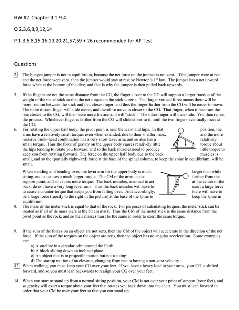
HW #2 Chapter 9.1-9.4 Q 2,3,6,8,9,12,14 P 1-3,6,8,15,16,19,20,21,57,59 + 26 recommended for AP Test Questions 2. The bungee jumper is not in equilibrium, because the net force on the jumper is not zero. If the jumper were at rest and the net force were zero, then the jumper would stay at rest by Newton’s 1st law. The jumper has a net upward force when at the bottom of the dive, and that is why the jumper is then pulled back upwards. 3. If the fingers are not the same distance from the CG, the finger closer to the CG will support a larger fraction of the weight of the meter stick so that the net torque on the stick is zero. That larger vertical force means there will be more friction between the stick and that closer finger, and thus the finger further from the CG will be easier to move. The more distant finger will slide easier, and therefore move in closer to the CG. That finger, when it becomes the one closest to the CG, will then have more friction and will “stick”. The other finger will then slide. You then repeat the process. Whichever finger is farther from the CG will slide closer to it, until the two fingers eventually meet at the CG. For rotating the upper half body, the pivot point is near the waist and hips. In that position, the arms have a relatively small torque, even when extended, due to their smaller mass, and the more massive trunk–head combination has a very short lever arm, and so also has a relatively small torque. Thus the force of gravity on the upper body causes relatively little torque about the hips tending to rotate you forward, and so the back muscles need to produce little torque to keep you from rotating forward. The force on the upper half body due to the back muscles is small, and so the (partially rightward) force at the base of the spinal column, to keep the spine in equilibrium, will be small. 6. 8. When standing and bending over, the lever arm for the upper body is much larger than while sitting, and so causes a much larger torque. The CM of the arms is also further from the support point, and so causes more torque. The back muscles, assumed to act at the center of the back, do not have a very long lever arm. Thus the back muscles will have to exert a large force to cause a counter-torque that keeps you from falling over. And accordingly, there will have to be a large force (mostly to the right in the picture) at the base of the spine to keep the spine in equilibrium. The mass of the meter stick is equal to that of the rock. For purposes of calculating torques, the meter stick can be treated as if all of its mass were at the 50 cm mark. Thus the CM of the meter stick is the same distance from the pivot point as the rock, and so their masses must be the same in order to exert the same torque. 9. If the sum of the forces on an object are not zero, then the CM of the object will accelerate in the direction of the net force. If the sum of the torques on the object are zero, then the object has no angular acceleration. Some examples are: a) A satellite in a circular orbit around the Earth. b) A block sliding down an inclined plane. c) An object that is in projectile motion but not rotating d) The startup motion of an elevator, changing from rest to having a non-zero velocity. 12. When walking, you must keep your CG over your feet. If you have a heavy load in your arms, your CG is shifted forward, and so you must lean backwards to realign your CG over your feet. 14. When you start to stand up from a normal sitting position, your CM is not over your point of support (your feet), and so gravity will exert a torque about your feet that rotates you back down into the chair. You must lean forward in order that your CM be over your feet so that you can stand up. Problems 1. If the tree is not accelerating, then the net force in all directions is 0. Fx FA FB cos110 FC x 0 110o FB FC x FA FB cos110 310 N 425 N cos110 164.6 N F y FA FB sin FC y 0 FC y FB sin110 425 N sin110 399.4 N FC FC2 x FC2 y tan 1 FC y FC x tan 1 FC 164.6 N 399.4 N 2 399.4 N 164.6 N 2 432.0 N 4.3 102 N 67.6o , 180o 67.6o 112.4o 112o And so FC is 430 N, at an angle of 112o clockwise from FA . 2. 3. The torque is the force times the lever arm. Fr 58 kg 9.8 m s 2 3.0 m 1.7 103 m N , clockwise Because the mass m is stationary, the tension in the rope pulling up on the sling must be mg, and so the force of the leg must be mg, upward. Calculate torques about the hip joint, counterclockwise torque taken as positive. See the free-body the leg. Note that the forces on the leg exerted by the hip joint because they do not exert a torque about the hip joint. mgx 2 Mgx1 0 m M x1 x2 15.0 kg 35.0 cm 80.5 cm mg x2 x1 6.52 kg Mg sling on the with diagram for are not drawn, 6. (a) Let m = 0. Calculate the net torque about the left end of the diving board, with counterclockwise torques positive. Since the equilibrium, the net torque is zero. FB FA F 1.0 m Mg 4.0 m 0 F 4Mg 4 58 kg 9.80 m s 2274 N 2.3 10 N 1.0 m B 2 board is in mg Mg 2.0 m 4.0 m 3 B Use Newton’s 2nd law in the vertical direction to find FA . F FB Mg FA y FA FB Mg 4Mg Mg 3Mg 3 58 kg 9.80 m s 2 1705 N 1.7 103 N (b) Repeat the basic process, but with m = 35 kg. The weight of the board will add more clockwise torque. FB 1.0 m mg 2.0 m Mg 4.0 m 0 FB 4 Mg 2mg 4 58 kg 2 35 kg 9.80 m s 2 2960 N 3.0 10 3 N F y FB Mg mg FA FA FB Mg mg 4 Mg 2mg Mg mg 3Mg mg 3 58 kg 35 kg 9.80 m s 2 2048 N 2.0 103 N 8. Let m be the mass of the beam, and M be the mass of the piano. Calculate torques about the left end of the beam, with counterclockwise torques positive. The conditions of equilibrium for the beam are used to find the forces that the support exerts on the beam. FR L mg 12 L Mg 14 L 0 FR 12 m 14 M g 12 140 kg 14 320 kg 9.80 m s 2 1.47 103 N F y FL FR mg Mg 0 FL m M g FR 460 kg 9.80 m s 2 1.47 103 N 3.04 103 N The forces on the supports are equal in magnitude and opposite in direction to the above two results. FR 1.5 103 N down FL 3.0 103 N down 15. The beam is in equilibrium, and so both the net torque and net force on it must be zero. From the free-body diagram, calculate the net torque about the center of the left support, with counterclockwise torques as positive. Calculate the net force, with upward as positive. Use those two equations to find FA and FB . F x x B FB 1 2 x3 x4 F1 x1 F2 x1 x2 F3 x1 x2 x3 mgx5 F1 x1 F2 x1 x2 F3 x1 x2 x3 mgx5 x1 x2 x3 x4 4300 N 2.0 m 3100 N 6.0 m 2200 N 9.0 m 250 kg 9.8 m s2 5.0 m 10.0 m 5925 N 5.9 10 N 3 F F A FB F1 F2 F3 mg 0 FA F1 F2 F3 mg FB 9600 N 250 kg 9.8 m s 2 5925 N 6125 N 6.1 103 N 16. From the free-body diagram, the conditions of equilibrium find the location of the girl (mass mC ). The 50-kg boy is mA , and the 35-kg girl by mB . Calculate torques about the see-saw, and take counterclockwise torques to be positive. force of the fulcrum on the see-saw F causes no torque center. are used to represented by L x mA g mC g F center of the mB g The upward about the m g L m gx m g L 0 A x 1 2 mA mB mC C L 1 2 B 1 2 50 kg 35 kg 1 25 kg 2 3.6 m 1.1 m 19. The person is in equilibrium, and so both the net torque and net force From the free-body diagram, calculate the net torque about the center with counterclockwise torques as positive. Use that calculation to location of the center of gravity, a distance x from the feet. x L-x FA FB must be zero. of gravity, find the mg F x F L x 0 B FA x A L mA g L mA L 35.1 kg FA FB mA g mB g mA mB 31.6 kg 35.1 kg The center of gravity is about 90.5 cm from the feet. 1.72 m 20. The beam is in equilibrium. Use the conditions of equilibrium to tension in the wire and the forces at the hinge. Calculate torques about take counterclockwise torques to be positive. FT sin l2 m1 g l1 2 m2 gl1 0 1 2 FT m1 gl1 m2 gl1 l2 sin 1 2 155 N 1.70 m 245 N 1.70 m 1.35 m sin 35.0o 9.05 101 m m1g l1 2 l2 l1 708.0 N 7.08 10 N 2 F F calculate the the hinge, and FT FH x FH x FT cos 0 FH x FT cos 708 N cos 35.0o 579.99 N 5.80 102 N y FH y FT sin m1 g m2 g 0 FH y m1 g m2 g FT sin 155 N 245 N 708 N sin 35.0o 6.092 N 6 N down m2g 21. (a) The pole is in equilibrium, and so the net torque on it must be zero. From the free-body diagram, calculate the net the lower end of the pole, with counterclockwise torques as that calculation to find the tension in the cable. The length L. FT h mg L 2 cos MgL cos 0 m FT FT h FP y 7.50 m cos 37 mg F Px 2 M gL cos h 6.0 kg 21.5 kg 9.80 m s 2 Mg y torque about positive. Use of the pole is x L cos o 424.8 N 4.25 102 N 3.80 m (b) The net force on the pole is also zero since it is in equilibrium. Write Newton’s 2nd law in both the x and y directions to solve for the forces at the pivot. F F x FP x FT 0 FP x FT 4.25 102 N y FP y mg Mg 0 FP y m M g 33.5 kg 9.80 m s 2 3.28 102 N 26. Write the conditions of equilibrium for the ladder, with torques taken bottom of the ladder, and counterclockwise torques as positive. l mg FW l sin mg 2 cos 0 FW 12 tan mg Fx FG x FW 0 FG x FW 12 tan Fy FG y mg 0 FG y mg For the ladder to not slip, the force at the ground FG x must be less than l sin FG y y mg maximum force of static friction. FG x FN FG y 1 2 mg tan FG x l cos mg Thus the minimum angle is min tan 1 1 2 . 1 2 about the FW tan tan 1 1 2 x or equal to the 57. Each crossbar in the mobile is in equilibrium, and so the net torque about the suspension point for each crossbar must be 0. Counterclockwise torques will be taken as positive. The suspension point is used so that the tension in the suspension string need not be known initially. The net vertical force must also be 0. The bottom bar: FCD mD gxD mC gxC 0 xD mC mD F y xC mD 17.50 cm 5.00 cm 3.50mD xD FCD mC g mD g 0 FCD mC mD g 4.50mD g xC mC g mD g The middle bar: F x CD CD mD mB xB 4.50 xCD mB gxB 0 FCD mB g xB 4.50mD g mB g xCD 0.885 kg 5.00 cm 0.06555 4.50 15.00 cm xB FBCD xCD xCD xB 2 6.56 10 kg mB g FCD mC 3.50mD 3.50 0.06555 kg 2.29 101 kg F y FBCD FCD mB g 0 FBCD FCD mB g 4.50mD mB g The top bar: mA gxA FBCD xBCD 0 mA 4.50mD mB gxBCD FABCD 4.50mD mB gxA 4.50 0.06555 kg 0.885 kg 59. xBCD xA xA 7.50 cm FBCD mA g 2.94 101 kg 30.00 cm (a) If the wheel is just lifted off the lowest level, then the forces on the wheel are the horizontal pull, its weight, and the FN at the corner. Take torques about the corner point, for the barely off the ground, being held in equilibrium. The contact corner exerts no torque and so does not enter the calculation. force has a lever arm of R R h 2 R h , and gravity has a x , found from the triangle shown. F 2R h Mg 2 F . h 2R h Mgx Rh Mgx Rh Mg R x h Mg Mg 2R h 2R h 2R h (b) The only difference is that now the pulling force has a lever arm of R h . Rh Mgx F R h 0 F FN x x R 2 R h h 2R h Mgx F 2 R h 0 xBCD F Mg h 2R h Rh x 30o Mg down mg down only contact force wheel just force at the The pulling lever arm of


