Ch9
advertisement
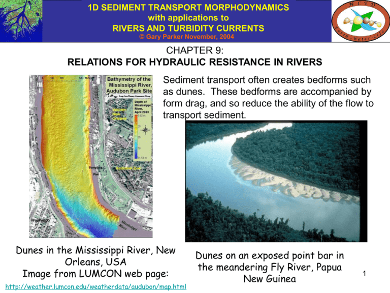
1D SEDIMENT TRANSPORT MORPHODYNAMICS with applications to RIVERS AND TURBIDITY CURRENTS © Gary Parker November, 2004 CHAPTER 9: RELATIONS FOR HYDRAULIC RESISTANCE IN RIVERS Sediment transport often creates bedforms such as dunes. These bedforms are accompanied by form drag, and so reduce the ability of the flow to transport sediment. Dunes in the Mississippi River, New Orleans, USA Image from LUMCON web page: http://weather.lumcon.edu/weatherdata/audubon/map.html Dunes on an exposed point bar in the meandering Fly River, Papua New Guinea 1 1D SEDIMENT TRANSPORT MORPHODYNAMICS with applications to RIVERS AND TURBIDITY CURRENTS © Gary Parker November, 2004 SKIN FRICTION AND FORM DRAG: THE CONCEPTS The drag force acting on a body can be decomposed into skin friction and form drag. The former is generated by the viscous shear stress acting tangentially to the body. The latter is generated by the normal stress (mostly pressure) acting on a body. The Newtonian constitutive relation for water is ij pij v,ij , v,ij ui u j x x i j Here ij denotes the stress acting in the jth direction on a face normal to the ith direction, p denotes the pressure, ij denotes the Kronecker delta ( = 1 if i = j and 0 if i j), ui = (u1, u2, u3) denotes the velocity vector and xi = (x1, x2, x3) denotes the position vector. The drag force Di on a body is given as Di jin jdS where ji is evaluated at the surface of the body, ni denotes a local unit vector outward normal to the surface of the body, and dS denotes an infinitesimal element of surface area. 2 1D SEDIMENT TRANSPORT MORPHODYNAMICS with applications to RIVERS AND TURBIDITY CURRENTS © Gary Parker November, 2004 SKIN FRICTION AND FORM DRAG: THE CONCEPTS contd. The drag force Di can be decomposed into a component due to skin friction Dsi and a component due to form drag Dfi as follows: Di Dsi Df i ui u j n jdS , D f i pnidS Dsi v, jin jdS x x j i Drag due to skin friction consists of that part of the drag that pulls the surface of the body tangentially. Form drag consists of that part of the drag that pushes the body in normally. Only the former is thought to directly contribute to sediment transport. Now in the diagrams below let Ds and D f denote the skin friction and form drag forces on the area element dS, n̂tx denote a unit tangential vector to the surface in the x direction and n̂n denote a unit vector normal to the surface. p u dDs n̂ tx dS z body u z x n̂tx dS dDf p body n̂ndS n̂n dS 3 1D SEDIMENT TRANSPORT MORPHODYNAMICS with applications to RIVERS AND TURBIDITY CURRENTS © Gary Parker November, 2004 SKIN FRICTION AND FORM DRAG: THE CONCEPTS contd. Let D denote the drag force in the flow direction and nx denote the component of the unit outward normal vector to the surface in the flow direction. At sufficiently high Reynolds number, the drag on a streamlined body is mostly skin friction. The drag on a blunt body behind which flow separation occurs is mostly form drag. (The pressure in the separation bubble equilibrates with the low pressure at the point of separation.) separation bubble p u z flow flow p p u D Ds u dS z body D Df p body nx dS 4 1D SEDIMENT TRANSPORT MORPHODYNAMICS with applications to RIVERS AND TURBIDITY CURRENTS © Gary Parker November, 2004 EINSTEIN DECOMPOSITION Einstein (1950); Einstein and Barbarossa (1952) When bedforms are not present, all of the drag on the bed is skin friction. This tangential drag force acts to pull the sediment along. When bedforms such as dunes are present, part of the drag is form drag associated with (most prominently) flow separation behind the dunes. Since this form drag is composed of stress that acts normal to the bed surface, it does not contribute directly to the motion of bed grains. As a result it is usually subtracted out in performing bedload calculations. H U separation bubble 5 1D SEDIMENT TRANSPORT MORPHODYNAMICS with applications to RIVERS AND TURBIDITY CURRENTS © Gary Parker November, 2004 EINSTEIN DECOMPOSITION contd. Consider an equilibrium (normal) flow over a bed with mean streamwise slope S that is covered with bedforms. The flow has average depth H and velocity U averaged over depth and the bedforms. The boundary shear stress averaged over the bedforms is given by the normal flow relation b C f U2 gHS H U 6 separation bubble 1D SEDIMENT TRANSPORT MORPHODYNAMICS with applications to RIVERS AND TURBIDITY CURRENTS © Gary Parker November, 2004 EINSTEIN DECOMPOSITION contd. Now smooth out the bedforms, “glue” the sediment to the bed so it remains flat but offers the same microscopic roughness as the case with bedforms, and run a flow over it with the same mean velocity U and bed slope S. In the absence of the bedforms, the resistance is skin friction only. Due to the absence of bedforms the skin friction coefficient Cfs and the flow depth Hs should be less than the corresponding values with bedforms. bs C f sU2 gHsS Skin friction + form drag H U Skin friction only Hs U separation bubble The difference between the two characterizes form drag. 7 1D SEDIMENT TRANSPORT MORPHODYNAMICS with applications to RIVERS AND TURBIDITY CURRENTS © Gary Parker November, 2004 EINSTEIN DECOMPOSITION contd. bf = b - bs = mean bed shear stress due to form drag of bedforms Cff = Cf – Cfs = friction coefficient associated with form drag Hf = H – Hs = mean depth associated with form drag bs C f sU2 gHsS bf Cf fU2 gHf S bs bf C f s C f f U2 gHs Hf S b C f U2 gHS Skin friction + form drag H U Skin friction only Hs U separation bubble The difference between the two characterizes form drag. 8 1D SEDIMENT TRANSPORT MORPHODYNAMICS with applications to RIVERS AND TURBIDITY CURRENTS © Gary Parker November, 2004 SKIN FRICTION Skin friction can be computed using the techniques developed in Chapter 5; where = 0.4 and r = 8.1, C 1/ 2 fs 1 Hs n11 ks 1/ 6 C or k s nk Ds90 1 / 2 fs Hs r ks , nk 2 bs C f sU2 gHsS Skin friction + form drag H U Skin friction only Hs U separation bubble The difference between the two characterizes form drag. 9 1D SEDIMENT TRANSPORT MORPHODYNAMICS with applications to RIVERS AND TURBIDITY CURRENTS © Gary Parker November, 2004 FORM DRAG OF DUNES: EINSTEIN AND BARBAROSSA (1952) One of the first relations developed to predict the form drag in rivers in which dunes predominate is that of Einstein and Barbarossa (1952). They obtained an empirical form for Cff as a function of s*, where bs u2s RgD 35 RgD 35 denotes the Shields number due to skin friction and D35 is the grain size such that 35 percent of a bed surface sample is finer. Note that u s bs 0.1 0.01 Cff s 35 0.001 0.0001 0.01 0.1 1 s35* 10 10 1D SEDIMENT TRANSPORT MORPHODYNAMICS with applications to RIVERS AND TURBIDITY CURRENTS © Gary Parker November, 2004 FORM DRAG OF DUNES: ENGELUND AND HANSEN (1967) The total shear velocity u*, shear velocity due to skin friction u*s and shear velocity due to bedforms u*f, and the associated Shields numbers are defined as u b , us bs bf , u f u2 RgD s50 u2s RgD s50 s , , u2f RgD s50 f Engelund and Hansen (1967) determined the following empirical relation for lowerregime form drag due to dune resistance; s 0.06 0.4 or thus f s 2 2 0.06 0.4 Note that bedforms are absent (skin friction only) when s* = *; bedforms are present when s* < *. The relation is designed to be used with the following skin friction predictor: 1 Hs k s 2 Ds65 n11 ks Engelund and Hansen (1967) also present a form drag relation for upperregime bedforms (antidunes). Cf s1/ 2 11 1D SEDIMENT TRANSPORT MORPHODYNAMICS with applications to RIVERS AND TURBIDITY CURRENTS © Gary Parker November, 2004 FORM DRAG OF DUNES: ENGELUND AND HANSEN (1967) contd. Engelund-Hansen Bedform Resistance Predictor 3 2.5 No form drag 2 x s E-H Relation No form drag 1.5 f 1 0.5 Engelund-Hansen s 0 0 0.5 1 1.5 x 2 2.5 3 12 1D SEDIMENT TRANSPORT MORPHODYNAMICS with applications to RIVERS AND TURBIDITY CURRENTS © Gary Parker November, 2004 DEPTH-DISCHARGE PREDICTIONS WITH THE FORM DRAG PREDICTOR OF ENGELUND AND HANSEN (1967) Form drag relations allow for a prediction of flow depth H and velocity U as a function of water discharge per unit width qw. In order to do this with the relation of Engelund and Hansen (1967) it is necessary to specify the stream slope S, bed material sizes Ds50 and Ds65, submerged specific gravity of the sediment R. The computation proceeds as follows for the case of normal flow, for which b = u*2 = gHS. Compute ks from Ds65. Assume a value (a series of values) of Hs. Assuming normal flow, compute u*s = (gHsS)1/2 and s* =u*s2/(RgDs50). Compute * from s* according to Engelund-Hansen. Again assuming normal flow, * = (HS)/(RDs50) so that H = RDs50*/S. Compute Czs = Cfs-1/2 from Hs/ks and the skin friction predictor. Compute the velocity U from the relation U/u*s = Czs. Compute the water discharge per unit width qw = UH. Plot H versus qw. 13 1D SEDIMENT TRANSPORT MORPHODYNAMICS with applications to RIVERS AND TURBIDITY CURRENTS © Gary Parker November, 2004 FORM DRAG OF DUNES: WRIGHT AND PARKER (2004) The form drag predictor of Engelund and Hansen (1967) tends to work well for sand-bed streams at laboratory scale. It also works well at small to medium field scale, i.e. in streams in which dunes give way to upper-regime plane bed before bankfull flow is achieved. It works rather poorly for large, low-slope sand-bed rivers, in which dunes are usually never washed out even at or above bankfull flow. Wright and Parker (2004) have modified it to accurately cover the entire range. s 0.05 0.7 Fr 0.7 0.8 U Fr Froude number gH This relation is designed to be used with the skin friction predictor C 1/ 2 fs 8.32 Hs strat k s 1 6 k s 3Ds90 where strat is a correction for flow stratification which can be set equal to unity in the absence of other information (see original reference). 14 1D SEDIMENT TRANSPORT MORPHODYNAMICS with applications to RIVERS AND TURBIDITY CURRENTS © Gary Parker November, 2004 COMPARISON OF FORM DRAG PREDICTORS AGAINST FIELD DATA The Niobrara and Middle Loup are small sand-bed streams. The Rio Grande is a middle-sized sand-bed stream. The Red, Atchafalaya and Mississippi Rivers are large sand-bed streams. 2.0 Middle Loup Rio Grande Atchafalaya Engelund-Hansen 1.8 1.6 2.0 Niobrara Red Mississippi 1.6 1.4 * sk s Middle Loup Rio Grande Atchafalaya New relation 1.8 Niobrara Red Mississippi 1.4 1.2 * sks * sk * 1.0 0.8 1.2 1.0 0.8 0.6 0.6 0.4 0.4 0.2 0.2 0.0 0.0 0.5 1.0 1.5 * 2.0 2.5 Engelund and Hansen (1967) 3.0 0.0 0.0 0.5 1.0 1.5 * Fr 0.7 Fr 2.0 2.5 0 .7 Wright and Parker (2004) 15 3.0 1D SEDIMENT TRANSPORT MORPHODYNAMICS with applications to RIVERS AND TURBIDITY CURRENTS © Gary Parker November, 2004 DEPTH-DISCHARGE PREDICTIONS WITH THE FORM DRAG PREDICTOR OF WRIGHT AND PARKER (2004) The relations can be written as: or alternatively as: H U 8.32 s gHsS ks H U 8.32 gHsS s ks 1 6 1 6 HS U 0.7 s 0.05 0.7 RD s50 gH RD s 50 H S g U 0 .7 20 / 13 s 0.05 0 . 7 5/4 The computation proceeds as follows for the case of normal flow, for which b = u*2 = gHS. The stratification correction is not implemented here for simplicity. Compute ks from Ds90. Assume a value (a series of values) of Hs. Assuming normal flow, compute u*s = (gHsS)1/2 and s* =u*s2/(RgDs50). Compute the velocity U from the skin friction predictor. Compute from the indicated equation. Compute H from the indicated equation. Compute the water discharge per unit width qw = UH. Plot H versus qw. 0 .8 16 1D SEDIMENT TRANSPORT MORPHODYNAMICS with applications to RIVERS AND TURBIDITY CURRENTS © Gary Parker November, 2004 PREDICTION OF BEDLOAD TRANSPORT IN A STREAM IN WHICH DUNES MAY BE PRESENT If dunes are not present, the calculation of bedload transport may proceed using the techniques of Chapter 7. If dunes are present, the calculation is based not on the total boundary shear stress b, but rather just that component due to skin friction bs. Thus in the case of relations for uniform sediment D, the following transformation must be made bs u2s RgD RgD s so that the bedload relation of e.g. Ashida and Michiue (1972) is recast as qb 17 s c s c , c 0.05 In the case of the normal flow HsD RD s and the calculation can proceed from the calculation of the depth-discharge relation. 17 1D SEDIMENT TRANSPORT MORPHODYNAMICS with applications to RIVERS AND TURBIDITY CURRENTS © Gary Parker November, 2004 SAMPLE PREDICTION OF FLOW AND BEDLOAD TRANSPORT Depth-Discharge and Bedload Calculator Input Parameters S 4.00E-05 D50 0.3 mm D90 0.6 mm nk 3 R 1.65 s HsS RD 50 H U 8.32 gHsS s ks Uses a) Wright-Parker formulation for flow resistance (without stratification correction) b) Ashida-Michiue formulation for bedload transport, bed slope median sediment size size such that 90% of the sediment is finer factor such that ks = nk Ds90 submerged specific gravity of sediment 1 6 RD s 50 H S qw 0.05 s 0 .7 5/4 g U UH 0 .7 20 / 13 Fr HS RD50 This calculation is implemented in: Rte-bookWPHydResAMBL.xls U gH u qb RgD50 D50 ( s 0.05)( s 0.05 ) gHS us gHsS Discard first three rows Input Hs (m) s* U (m/s) H (m) qw (m2/s)* s*/* Fr u* (m/s) u*s (m/s) qb (m2/s) 0.800 0.0646 0.4072 0.008 0.254 0.1036 0.0206 3.145 0.258 0.00999 0.01772 1.60E-07 Discard results whenever s*/* > 1 0.900 0.0727 0.4405 0.014 0.544 0.2397 0.0440 1.654 0.191 0.01461 0.01879 3.72E-07 1.000 0.0808 0.4725 0.02 0.906 0.4279 0.0732 1.104 0.159 0.01885 0.01981 6.64E-07 1.100 0.0889 0.5035 0.027 1.323 0.6664 0.1069 0.831 0.14 0.02279 0.02078 1.03E-06 1.200 0.0970 0.5336 0.034 1.788 0.9539 0.1444 0.671 0.127 0.02648 0.0217 1.47E-06 1.300 0.1051 0.5629 0.042 2.29 1.2891 0.1851 0.568 0.119 0.02998 0.02259 1.97E-06 1.400 0.1131 0.5914 0.049 2.826 1.6712 0.2284 0.495 0.112 0.0333 0.02344 2.53E-06 1.500 0.1212 0.6192 0.057 3.39 2.0994 0.2740 0.442 0.107 0.03647 0.02426 3.15E-06 1.600 0.1293 0.6464 0.066 3.98 2.5729 0.3216 0.402 0.103 0.03952 0.02506 3.83E-06 1.700 0.1374 0.6731 0.074 4.592 3.0912 0.3711 0.37 0.1 0.04245 0.02583 4.57E-06 1.800 0.1455 0.6992 0.083 5.225 3.6536 0.4222 0.344 0.098 0.04528 0.02658 5.35E-06 1.900 0.1535 0.7249 0.092 5.876 4.2598 0.4749 0.323 0.095 0.04802 0.0273 6.19E-06 2.000 0.1616 0.7501 0.101 6.545 4.9092 0.5289 0.306 0.094 0.05068 0.02801 7.08E-06 2.100 0.1697 0.7749 0.11 7.229 5.6015 0.5841 0.291 0.092 0.05326 0.02871 8.01E-06 2.200 0.1778 0.7993 0.119 7.927 6.3362 0.6406 0.278 0.091 0.05577 0.02938 8.99E-06 2.300 0.1859 0.8234 0.129 8.639 7.1130 0.6981 0.266 0.089 0.05822 0.03004 1.00E-05 2.400 0.1939 0.8471 0.138 9.364 7.9316 0.7567 0.256 0.088 0.06062 0.03069 1.11E-05 18 2.500 0.2020 0.8704 0.148 10.1 8.7917 0.8162 0.248 0.087 0.06296 0.03132 1.22E-05 The basis for the calculation is a large sand-bed stream. The calculation uses Wright-Parker (without stratification correction) and Ashida-Michiue. 1D SEDIMENT TRANSPORT MORPHODYNAMICS with applications to RIVERS AND TURBIDITY CURRENTS © Gary Parker November, 2004 DEPTH-DISCHARGE AND BEDLOAD RELATION FOR SAMPLE CALCULATION Wright-Parker depth-discharge predictor: Ashida-Michiue bedload transport relation 10.0 1.4E-05 9.0 1.2E-05 8.0 1.0E-05 2 H (m), qb (m /s) 7.0 6.0 8.0E-06 5.0 6.0E-06 4.0 3.0 H qb 4.0E-06 2.0 2.0E-06 1.0 0.0 0.0 2.0 4.0 6.0 qw (m2/s) 8.0 0.0E+00 10.0 19 1D SEDIMENT TRANSPORT MORPHODYNAMICS with applications to RIVERS AND TURBIDITY CURRENTS © Gary Parker November, 2004 A BULK PREDICTOR FOR DEPTH-DISCHARGE RELATIONS The Brownlie (1982) empirical depth-discharge predictor has been demonstrated to be accurate for both laboratory and field sand-bed streams. It takes the lowerregime form 1 0.6539 0.09188 0.1050 Ĥ 0.3724 S (q̂w S) S g and the upper-regime form where Ĥ 0.2836 S1 (q̂w S)0.6248 S0.08750 0g.08013 Ĥ H Ds50 , q̂w qw gDs50 Ds50 Once H is known U = qw/H can be computed. It is then possible to back-calculate Hs from any appropriate relation for skin friction and the normal flow assumption, e.g. 1/ 6 Hs U r gHsS ks Once Hs is known, s* = (HsS)/(RDs50) and thus the bedload transport rate can be computed. A discriminator between lower regime and upper regime can 20 be found in the original reference. 1D SEDIMENT TRANSPORT MORPHODYNAMICS with applications to RIVERS AND TURBIDITY CURRENTS © Gary Parker November, 2004 ANOTHER BULK PREDICTOR FOR FLOW RESISTANCE The flow predictor of Karim and Kennedy (1981) takes the following form: U og10 RgD 50 q t 0.9045 0.1665 og10 RgD D 50 50 u q uD50 t 0.0831og10 og10 og10 RgD D vs 50 50 u u D 0.2166 og10 og10 50 vs H u og10 S 103 og10 0.0411og10 D50 vs where qt denotes the total volume bed material load per unit width. Karim and Kennedy’s predictor for qt is presented in Chapter 11. 21 1D SEDIMENT TRANSPORT MORPHODYNAMICS with applications to RIVERS AND TURBIDITY CURRENTS © Gary Parker November, 2004 GENERALIZATION TO GRADUALLY VARIED FLOWS The preceding calculations are predicated on the assumption of normal flow. In the case of gradually varied flow, the equation to be solved is dH S S f dx 1 Fr 2 In the calculation of gradually varied flow the actual slope S should be replaced by the friction slope Sf in the relations for skin friction and form drag: U2 S f Cf b b gSf H gH gH For example, the relations of Wright and Parker (without stratification correction) become Hs qw 8.32 H gHsS f ks 1 6 0.7 HsS f HS q f w 0.05 0.7 3 / 2 RD s50 g H RD 50 0 .8 22 1D SEDIMENT TRANSPORT MORPHODYNAMICS with applications to RIVERS AND TURBIDITY CURRENTS © Gary Parker November, 2004 GENERALIZATION TO GRADUALLY VARIED FLOWS contd. The flow is assumed to be subcritical. The depth H is assumed to be known at the downstream point H2; it is to be computed at the upstream point H1. The formulation can be discretized as 1 2 1 2 Sf1 Sf 2 1 x x H1 H2 x 2 2 qw qw 2 1 1 3 3 gH gH 1 2 flow Now since qw and H2 are known, Hs1 and Sf1 can be computed (iteratively) from the two relations H1 H2 x x1 x2 H qw 8.32 s1 H1 gHs1S f 1 ks 1 6 0.7 H S q Hs1S f 1 1 f 1 w 0.05 0.7 3/2 RD 50 RD s50 g H1 0.8 23 1D SEDIMENT TRANSPORT MORPHODYNAMICS with applications to RIVERS AND TURBIDITY CURRENTS © Gary Parker November, 2004 GENERALIZATION TO GRADUALLY VARIED FLOWS contd. Once all quantities at x2 are computed, H1, Hs1 and Sf1 can be computed iteratively from the following three equations. 1 2 1 2 Sf1 Sf 2 1 x H1 H2 x x 2 2 qw qw 2 1 1 gH13 gH32 flow Hs1 qw 8.32 H1 gHs1S f 1 ks H1 1 6 H2 0.7 Hs1S f 1 H S q 1 f 1 w 0.05 0.7 3/2 RD 50 RD s50 g H1 x 0.8 24 x1 x2 1D SEDIMENT TRANSPORT MORPHODYNAMICS with applications to RIVERS AND TURBIDITY CURRENTS © Gary Parker November, 2004 REFERENCES FOR CHAPTER 9 Ashida, K. and M. Michiue, 1972, Study on hydraulic resistance and bedload transport rate in alluvial streams, Transactions, Japan Society of Civil Engineering, 206: 59-69 (in Japanese). Brownlie, W. R., 1981, Prediction of flow depth and sediment discharge in open channels, Report No. KH-R-43A, W. M. Keck Laboratory of Hydraulics and Water Resources, California Institute of Technology, Pasadena, California, USA, 232 p. Einstein, H. A., 1950, The Bed-load Function for Sediment Transportation in Open Channel Flows, Technical Bulletin 1026, U.S. Dept. of the Army, Soil Conservation Service. Einstein, H. A and Barbarossa, N. L., 1952, River Channel Roughness, Journal of Hydraulic Engineering, 117. Engelund, F. and E. Hansen, 1967, A Monograph on Sediment Transport in Alluvial Streams, Technisk Vorlag, Copenhagen, Denmark. Karim, F., and J. F. Kennedy, 1981, Computer-based predictors for sediment discharge and friction factor of alluvial streams, Report No. 242, Iowa Institute of Hydraulic Research, University of Iowa, Iowa City, Iowa. Wright, S. and Parker, G., 2004, Flow resistance and suspended load in sand-bed rivers: simplified stratification model, Journal of Hydraulic Engineering, 130(8), 796-805. 25


