In constructive interference
advertisement
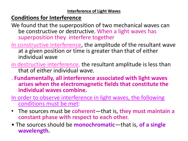
Interference of Light Waves Conditions for Interference We found that the superposition of two mechanical waves can be constructive or destructive. When a light waves has superposition they interfere together In constructive interference, the amplitude of the resultant wave at a given position or time is greater than that of either individual wave in destructive interference, the resultant amplitude is less than that of either individual wave. . Fundamentally, all interference associated with light waves arises when the electromagnetic fields that constitute the individual waves combine. In order to observe interference in light waves, the following conditions must be met: • The sources must be coherent—that is, they must maintain a constant phase with respect to each other. • The sources should be monochromatic—that is, of a single wavelength. Young’s Double-Slit Experiment The light emerging from the two slits is coherent because a single source produces the original light beam and the two slits serve only to separate the original beam into two parts. If the light travelled only in its original direction after passing through the slits the waves would not overlap and no interference pattern would be seen. • These two slits serve as a pair of coherent light sources because waves emerging from them originate from the same wave front and therefore maintain a constant phase relationship. The light from S1 and S2 produces on a viewing screen a visible pattern of bright and dark parallel bands called fringes (Fig. 37.2b). • When the light from S1 and that from S2 both arrive at a point on the screen such that: constructive interference occurs at that location, a bright fringe appears combines destructively at any location on the screen, a dark fringe results. • The viewing screen is located a perpendicular distance L from the barrier containing two slits, S1 and S2. These slits are separated by a distance d, and the source is monochromatic • a wave from the lower slit must travel farther than a wave from the upper slit by a distance r2-r1=d sin θ • This distance is called the path difference δ (lowercase Greek delta). • The value of δ determines whether the two waves are in phase when they arrive at point P. • If δ is either zero or some integer multiple of the wavelength, then the two waves are in phase and constructive interference results condition for bright fringes • The number m is called the order number. • The central bright fringe at θ=0 is called the zeroth-order maximum. • The first maximum on either side, where m= ±1, is called the first-order maximum, and so forth. • When δ is an odd multiple of λ/2, the two waves arriving at point P are 180° out of phase and give rise to destructive interference condition for dark fringes. • It is useful to obtain expressions for the positions along the screen of the bright and dark fringes measured vertically from O to P. In addition to our assumption that L >>d, we assume d >>λ. These can be valid assumptions because in practice L is often on the order of 1 m, d a fraction of a millimetre, and λ a fraction of a micrometer for visible light. Under these conditions, θ is small; thus, we can use the small angle approximation sin θ ≈ tan θ. Then, from triangle OPQ in Figure • Solving Equation 37.2 for sin θ and substituting the result into Equation 37.4, we see that the positions of the bright fringes measured from O are given by the expression • Using Equations 37.3 and 37.4, we find that the dark fringes are located at • Young’s double-slit experiment provides a method for measuring the wavelength of light. • Example: • In a double-slit arrangement of Figure 37.5, d = 0.150 mm, L = 140 cm, λ=643 nm, and y= 1.80 cm. (a) What is the path difference δ for the rays from the two slits arriving at P ? (b) Express this path difference in terms of λ (c) Does • P corresponds to a maximum, a minimum, or an intermediate condition? • Solution: • Example: • A light source emits visible light of two wavelengths: λ = 430 nm and λ = י510 nm. The source is used in a double-slit interference experiment in which L = 1.50 m and d = 0.025 0 mm. Find the separation distance between the third-order bright fringes. • Solution • With m = 3, we find that the fringe positions corresponding to these two wavelengths are Intensity Distribution of the Double-Slit Interference Pattern Note that the edges of the bright fringes in Figure 37.2b are not sharp—there is a gradual change from bright to dark. So far we have discussed the locations of only the centres of the bright and dark fringes on a distant screen. We now calculate the distribution of light intensity associated with the double-slit interference pattern. • The slits have the same angular frequency ω and a constant phase difference ɸ. • The total magnitude of the electric field at point P on the screen in Figure 37.6 is the superposition of the two waves. • Assuming that the two waves have the same amplitude E0, we can write the magnitude of the electric field at point P due to each wave separately as • Although the waves are in phase at the slits, their phase difference ɸ at P depends on the path difference δ=r2 -r1 =d sin θ • A path difference of λ (for constructive interference) corresponds to a phase difference of 2π rad. A path difference of δ is the same fraction of λ as the phase difference ɸ is of 2π. We can describe this mathematically With the ratio • Which give Phase difference • This equation tells us precisely how the phase difference ɸ depends on the angle θ. • we can obtain the magnitude of the resultant electric field at point P : Phase difference • To simplify this expression, we use the trigonometric identity • Taking A = ωt + ɸ and B= ωt, we can write • This result indicates that 1) The electric field at point P has the same frequency ω as the light at the slits 2) The amplitude of the field is multiplied by the factor 2 cos (ɸ/2). 3) the condition for maximum constructive interference occurs when ɸ= 0, 2π, 4π, . . ., the magnitude of the electric field at point P is 2E0 • The total destructive interference occurs when ɸ= π, 3π, 5π, . . ., the magnitude of the electric field at point P is zero. The intensity of a wave is proportional to the square of the resultant electric field magnitude at that point and The average light intensity at point P as • Where Imax is the maximum intensity on the screen and the expression represents the time average. Substituting the value for ɸ given by Equation 37.8 into this expression, we find that 37.12 • Alternatively, because sin θ ≈y/L for small values of θ in Figure 37.5, we can write Equation 37.12 in the form 37.13 • A plot of light intensity versus d sinθ is given in Figure • EXAMPLE A screen is separated from a double-slit source by 1.20 m. The distance between the two slits is 0.030 0 mm. The second-order bright fringe (m =2) is measured to be 4.50 cm from the center line. Determine (a) the wavelength of the light and (b) the distance between adjacent bright fringes. • Solution a) b) • EXAMPLE Young’s double-slit experiment is performed with 589nm light and a distance of 2.00 m between the slits and the screen. The tenth interference minimum is observed 7.26 mm from the central maximum. Determine the spacing of the slits. • EXAMPLE Two narrow, parallel slits separated by 0.250 mm are illuminated by green light (λ =546.1 nm). The interference pattern is observed on a screen 1.20 m away from the plane of the slits. Calculate the distance (a) from the central maximum to the first bright region on either side of the central maximum and (b) between the first and second dark bands. Solution CHANGE OF PHASE DUE TO REFLECTION • Another simple, yet ingenious, arrangement for producing an interference pattern with a single light source is known as Lloyd’s mirror. • Light waves can reach the viewing point P either by the direct path SP or by the path involving reflection from the mirror. The reflected ray can be treated as a ray originating at the source S´ behind the mirror. Source S´, which is the image of S, can be considered a virtual source. • At points far from the source, an interference pattern due to waves from S and S´ is observed, just as for two real coherent sources. • the positions of the dark and bright fringes are reversed relative to the patterns of Young’s experiment. • because the coherent sources S and S´ differ in phase by 180°, a phase change produced by reflection. • To illustrate the point further. • consider P´, the point where the mirror intersects the screen. This point is equidistant from S and S´. • If path difference alone were responsible for the phase difference, a bright fringe would be observed at P (because the path difference is zero for this point. • corresponding to the central fringe of the twoslit interference pattern. Instead, we observe a dark fringe at P, from which we conclude that a 180° phase change must be produced by reflection from the mirror. • In general, an electromagnetic wave undergoes a phase change of 180° upon reflection from a medium that has an index of refraction higher than the one in which the wave was travelling. • An analogy can be drawn between reflected light waves and the reflections of a transverse wave on a stretched string when the wave meets a boundary, as in Figure • when it is reflected from the boundary of a denser string or from a rigid barrier and undergoes no phase change when it is reflected from the boundary of a less dense string. • Similarly, an electromagnetic wave undergoes a 180° phase change when reflected from the boundary of a medium with index of refraction higher than the one in which it has been travelling. • There is no phase change when the wave is reflected from a boundary leading to a medium of lower index of refraction. The transmitted wave that crosses the boundary also undergoes no phase change. INTERFERENCE IN THIN FILMS Interference effects are commonly observed in thin films, such as the thin surface of a soap bubble or thin layers of oil on water. The varied colours observed when incoherent white light is incident on such films result from the interference of waves reflected from the two surfaces of the film. Assume that the light rays travelling in air are nearly normal to the two surfaces of the film. To determine whether the reflected rays interfere constructively or destructively, we first note the following facts: 1. An electromagnetic wave travelling from a medium of index of refraction n1 toward a medium of index of refraction n2 undergoes a 180° phase change on reflection when n2 > n1. There is no phase change in the reflected wave if n2 < n1. 2. The wavelength of light λn in a medium with index of refraction n is where λ is the wavelength of light in vacuum. • We apply these rules to the film of Figure 24.7 • ray 1, which is reflected from the upper surface A, undergoes a phase change of 180° with respect to the incident wave. • Ray 2, which is reflected from the lower surface B, undergoes no phase change with respect to the incident wave. Therefore, ray 1 is 180° out of phase with respect to ray 2, which is equivalent to a path difference of λn /2. we must also consider the fact that ray 2 travels an extra distance of 2t before the waves recombine in the air above the surface. • if 2t =λn/2, then rays 1 and 2 recombine in phase, and constructive interference results. • In general, the condition for constructive interference in thin films is • This condition takes into account two factors: (1) the difference in path length for the two rays (the term mλn) and (2) the 180° phase change upon reflection (the term λn/2). Because λn =λ/n, we can write Equation 24.8 in the form • If the extra distance 2t travelled by ray 2 is a multiple of λn, then the two waves combine out of phase and the result is destructive interference. The general equation for destructive interference in thin films is • Equations 24.9 and 24.10 for constructive and destructive interference are valid when there is only one phase reversal.(nair less than nfilm ) • If the film is placed between two different media, one of lower refractive index than the film and one of higher refractive index, Equations 24.9 and 24.10 are reversed:
