Alternating Current Circuits: RMS, Capacitors, Inductors
advertisement
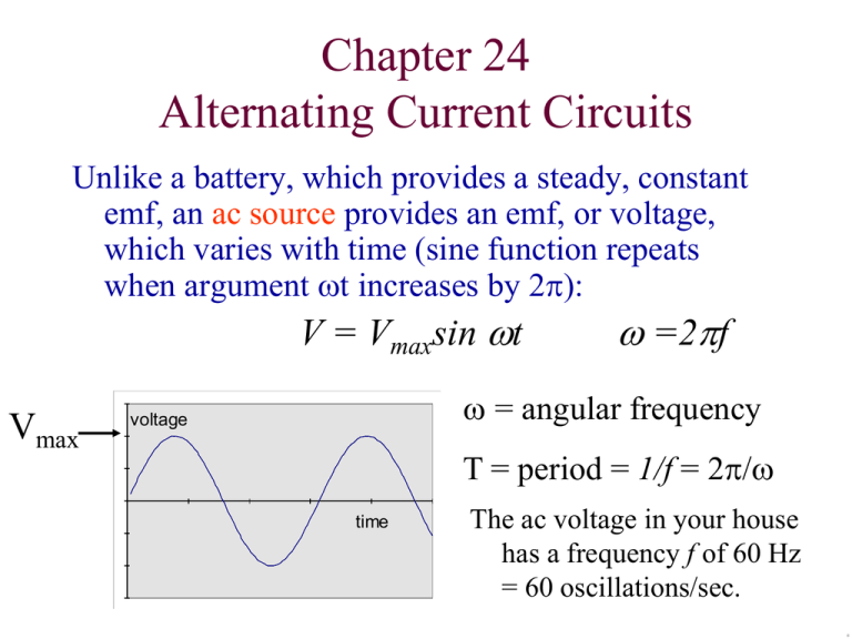
Chapter 24 Alternating Current Circuits Unlike a battery, which provides a steady, constant emf, an ac source provides an emf, or voltage, which varies with time (sine function repeats when argument wt increases by 2p): V = Vmaxsin wt Vmax w =2pf w = angular frequency voltage T = period = 1/f = 2p/w time The ac voltage in your house has a frequency f of 60 Hz = 60 oscillations/sec. Resistor in an ac circuit The voltage across the resistor is changing with time, so the current through the resistor must also be time-varying. I = V/R = Imax sin wt Notice that as the voltage changes sign, the current changes direction. The voltage and the current are in phase. They peak at the same time. rms Values It is useful to compare ac circuits and dc circuits. We cannot use, however, the average ac current or voltage which are both zero. Instead we must use the root mean square or rms values. I rm s I m ax , 2 V rm s V m ax 2 The rms value of current or voltage in an ac circuit can be compared to the equivalent quantities in a simple dc circuit. Vrms = IrmsR Pav = Irms2R = Vrms2/R Root Mean Square Voltage and Current V (t ) Vmax sin(wt ) I (t ) V (t ) / R (Vmax / R) sin(wt ) V2 Power P I 2R R 2 Vmax P sin 2 (wt ) R 2 Vmax 1 2 P Vrms / R, R 2 Vrms VMax / 2 Vrms = Square root of the mean (average) of V-squared. Average AC Power consumed by a resistor 2 2 independent of form of V vs t curve P Vrms / R I rms R Home Circuits • US standard: 120 V, 60 Hz AC • Vrms = 120 V, Vmax = (2) 120 V =170 V • Circuit Breakers trip at Irms = 15 A – Imax = (2) 15 A =21.2 Amp • Maximum power in typical home circuit: • P = Irms Vrms < (15A) (120 V) = 1800 W • Clothes Dryers, AC units frequently require higher power: – Higher current circuits (20 A), and higher voltage: • Vrms = 240 V Walker Problem 5 pg. 812 A 3.33-kW resistor is connected to a generator with a maximum voltage of 101 V. Find (a) the average and (b) the maximum power delivered to this circuit. Vrms Vmax / 2 101V / 1.414 71.4V 2 P Vrms / R (71.4V ) 2 /(3330 W) 1.53W 2 PMax Vmax / R (101V ) 2 /(3330 W) 3.06W Capacitors in ac circuits The “resistance” of the capacitor to current in the circuit is known as capacitive reactance XC = 1/(wC) SI unit of reactance: Ohm (W) = s/F Vrms = IrmsXC OR Vmax = ImaxXC The voltage lags behind the current by 90°. V=Q/C: When I>0, capacitor is charging, When I<0, capacitor is dis-charging. The average power consumed by a capacitor in an ac circuit is zero. Every ½ cycle capacitor stockpiles energy; During next ½ cycle capacitor disharges energy to circuit. Walker Problem 14, pg. 813 An rms voltage of 10.0 V with a frequency of 1.00 kHz is applied to a 0.395-mF capacitor. (a) What is the rms current in this circuit? (b) By what factor does the current change if the frequency of the voltage is doubled? (c) Calculate the current for a frequency of 2.00 kHz. X C 1 /(wC ) 1 403 s F (2p )(1000 Hz)(0.395 10 6 F ) s V 403 403 403W C /V A I rms Vrms / X C 10.0V /( 403W) 0.0248 A 24.8mA If frequency is doubled, XC drops by factor of 2, Current is doubled: Irms = 49.6 mA @2.00 kHz Inductors in AC circuits The “resistance” of the inductor to current in the circuit is known as inductive reactance XL = wL SI unit of reactance: Ohm (W) = H/s Vrms = IrmsXL OR Vmax = ImaxXL The voltage leads the current by 90°. The voltage required to drive the current is maximized when the current is changing the fastest. The average power consumed by an inductor in an ac circuit is zero. Walker Problem 29, pg. 813 What is the rms current in a 125-mH inductor when it is connected to a 60.0-Hz generator with an rms voltage of 115 Hz? Ground Fault Interupter • The principle of magnetic flux is exploited in an important electrical safety circuit • As long as the input and output currents are equal and opposite, there is zero flux in through the secondary. • If current flows through an alternate path to ground (e.g. through your body!!) the imbalance produces a magnetic flux, which induces an EMF in the sensing coil and trips the Circuit Breaker. • This can save your life. RC circuits: Filters & AC-coupling I I • In a series RC circuit, the same current flows from the generator, through the resistor, onto the top plate of the capacitor, and out of the bottom plate of the capacitor. – This is true for both AC and DC power. • The voltage drop across the resistor is in phase with the current. • The voltage drop across the capacitor lags the current by ¼ oscillation. • The resistance and the capacitive reactance combine “in quadrature” to yield the effective AC impedance 1 Z R 2 X C2 R 2 wC 2 RC Circuit: Equivalent Circuit = Vrms I rms Vrms / Z Z 2 R X C2 1 R wC 2 2 Irms Z RC Circuit: Filter Irms Vrms Vout • Analyze output voltage, as a function of frequency w of source. I rms Vrms / Z Vout ,rms I rms X C Vrms Vout ,rms Vrms 1 /(wC ) XC Z 1 R wC 2 2 Vrms 1 wRC 2 1 • For w >> 1/(RC), Vout 0 • For w << 1/(RC), Vout Vrms RC Circuit: Filter VDC Irms Vout Vrms • RC Circuit filters out unwanted noise (Vrms at frequency w/2p) from a DC power supply (VDC). • Treat the high frequency noise and DC supply independently – For w >> 1/(RC), Vout(w) 0 – For w << 1/(RC), Vout VDC RC Circuit: AC Signal Coupling C Vout Vrms Irms • By looking at the signal across the resistor (instead of the capacitor) an AC circuit removes any DC bias from the input, and transmits the high frequency signal to the output I rms Vrms / Z Z X C2 R 2 Vout ,rms I rms R Vrms Vout ,rms Vrms R Z R 2 1 2 R wC Vrms 1 2 1 wRC 1 AC Coupling C Vout Vrms Irms • At high frequency, w>>1/(RC), the capacitor acts as a short circuit, Vout = Vrms • At low frequency w << 1/(RC), the capacitor acts as an open circuit, Vout 0 Vout ,rms Vrms 1 2 1 1 wRC Phasors • V=V0sin(wt) can be thought of as the yprojection of a vector of length V0 rotating in a imaginary x-y plane with angular frequency w. Why bother? • For a Resistor, I = V/R, – I in phase with V. • For a Capacitor IRMS = VRMS (wC), – I leads V by ¼ oscillation = 90° on phasor plot • For an Inductor IRMS = VRMS / (wL) – I lags V by ¼ oscillation = 90° on phasor plot • Also, eip = -1 is a really cool theorem Phasors We can represent the current and the voltage across the inductor (VL), capacitor (VC) and resistor (VR) by vector diagrams called phasors. The current I is always parallel to VR. In this graph, the phasor is frozen at the moment I(t) is parallel to x-axis. The voltage vectors indicate their phase relative to the current: VL VR VC I V f VR VL- VC f is the phase angle between the current and the voltage in the circuit VL VC I X L X C , cos f VR R tan f V Z VR IR Walker Problem 22, pg. 813 A 65.0-Hz generator with an rms voltage of 115 V is connected in series to a 3.35-kW resistor and a 1.50-mF capacitor. Find (a) the rms current in the circuit and (b) the phase angle, f, between the current and the voltage. VR= IR VC= I XC = I/(wC) I 115 V 115V ( IR ) 2 ( IX C ) 2 I R 2 X C2 IZ I 115V / Z 115V / (3350 W) 2 1 /[ 2p (65 / s )(1.50 10 6 F )]2 I 115V /(3726 W) 30.9 10 3 A tan f ( IX C ) /( IR ) X C / R 1 /(wRC ), f 64.0 RC Circuit, Alternating Current I(t) erms • • • • • • VR = I(t) R VC = Q(t)/C VR,rms= Irms R VC,rms = Irms /(wC) erms = Irms Z Z = [R2+XC2]1/2 RC Circuit Current in resistor R equals current flowing onto capacitor. Positive current means the capacitor charge is increasing. 2.50 2.00 1.50 1.00 Volts 0.50 0.00 0.00 -0.50 1.57 3.14 4.71 6.28 7.85 9.42 11.00 12.57 14.14 15.71 -1.00 -1.50 -2.00 -2.50 w t V_R = IR V_C=I X_C V_R+V_C ref pts a) b) c) d) e) f) When is the capacitor charge increasing? From wt = 0 to 1.57 From wt = 1.57 to 3.14 a) and b) From wt = 3.14 to 4.71 From wt = 4.71 to 6.28 a) and e) RC Circuit Current in resistor R equals current flowing onto capacitor. Positive current means the capacitor charge is increasing. 2.50 2.00 1.50 1.00 Volts 0.50 0.00 0.00 -0.50 1.57 3.14 4.71 6.28 7.85 9.42 11.00 12.57 -1.00 -1.50 -2.00 -2.50 w t V_R = IR V_C=I X_C V_R+V_C ref pts 14.14 15.71 When the capacitor charge is maximum: a) The current is also maximum b) The current is at its negative maximum c) The current is increasing d) The current is zero. RC Circuit Phase shift 3.00 Volts 2.00 1.00 0.00 -1.000.00 1.57 3.14 4.71 6.28 7.85 9.42 11.00 12.57 14.14 -2.00 -3.00 w t V_R = IR V_C=I X_C I (t ) 2I rms cos(wt ) I Q (t ) 2 rms sin(wt ) w Q (t ) C 1 2I rms R cos(wt ) sin(wt ) wC 1 R 2I rms Z cos(wt ) sin(wt ) wCZ Z e (t ) I (t ) R V_R+V_C ref pts Z R2 X C 2 cosf R / Z sin f X C / Z e (t ) 2I rms Z cos(wt f ) e rms I rms Z 15.71 RC Circuit 3.00 Volts 2.00 1.00 0.00 -1.000.00 1.57 3.14 4.71 6.28 7.85 9.42 11.00 12.57 14.14 15.71 -2.00 -3.00 w t V_R = IR V_C=I X_C e ref pts VR VR VC V_R+V_C e VC VC RL Circuit & Phasors • The source determines e and w, • The circuit determines the magnitude and phase of the current. e e LR Circuit, Oscillating EMF LR Circuit 2.50 2.00 1.50 1.00 Volt 0.50 0.00 0.00 -0.50 1.57 3.14 4.71 6.28 7.85 9.42 11.00 12.57 -1.00 -1.50 -2.00 -2.50 wt V_R = IR V_L = I X_LI V_R+V_L When is the current decreasing most rapidly? a) At wt=0 c) At wt = p = 3.14 b) At wt = p/2 = 1.57 d) At wt = 3 p /2 = 4.71 14.14 15.71 LC Circuit Total Voltage drop around loop is zero, I XL – I X C = 0 wL – 1/(wC) = 0 w2=1/(LC) a) Initially, Capacitor is charged, current starts to flow, carrying charge from top plate to bottom plate, through inductor. b) Capacitor is completely discharged, but inductance opposes any change in current. Current keeps flowing, building up c) Positive charge on Bottom plate. This completes one half cycle in time p/w. LC Circuit (no dissipation) A LC circuit is like a mass on a spring: mass Inductance Kinetic Energy Magnetic Energy Spring constant 1/Capacitance Potential Energy Electric Energy The RLC Series Circuit The effective resistance of the circuit is given by the impedance Z: Z R 2 ( X L X C )2 VIZ Imax = Vmax / Z Irms = Vrms / Z SI unit of impedance: ohm The RLC Series Circuit Z R 2 ( X L X C )2 I V / Z VR IR V ( R / Z ) VC IX C V ( X C / Z ) VL IX L V ( X L / Z ) w2=1/(LC) • Resonance XL=XC VL=VC = VR XC /R If XC >>R, at resonance, then VC >>VR VL VR VC Walker Problem 40, pg. 814 Find the rms voltage across each element in an RLC circuit with R = 9.9 kW, C = 0.15 mF, and L = 25 mH. The generator supplies an rms voltage of 115 V at a frequency of 60.0 Hz. (b) What is the phase angle between the voltage and the current in the circuit? Resonance in a Series RLC Circuit The current in a series RLC circuit is Vmax I max Z Vmax R2 ( X L X C )2 The current will be maximum when XL = XC at a resonance frequency w of 1 w0 LC Z (w0 ) R Energy Storage at Resonance • Energy in Inductor EL= (1/2) L(Irms)2 = (1/2) L(Irms)2 • Energy lost in one cycle ER= PT = (Irms)2R(2p/w) = (1/2) L(Irms)2 • [Energy Stored]/[Energy dissipated in one cycle] Oscillator ‘Q-value’ = EL / ER= Lw/4pR) At Resonance w = 1/(LC)1/2 ‘Q-Value’ = (L/C)1/2 /(4pR) Jefferson Lab `Q-Value’=109 RLC oscillator in lab, L = 0.010H, R=15 W, C = 1.00e-4F ‘Q-Value’ = (0.01H/0.0001F) 1/2 /(4p 15W) = (10W)/(15W 4p) = 0.4 Resonance frequency = 1/[2p(LC)1/2] = 160 Hz Jefferson Lab Accelerator • RLC Circuit: f = 1.5 GHz – Free oscillation decays by factor e=2.718 in 109 oscillations – “Like a church bell that rings for a month”: (109)/(440/sec) =26 days
