Wireless Transceiver nRF24L01
advertisement
Wireless Transceiver nRF24L01
2015 Adrian Krag
Overview
This circuit is a low cost 2.4 GHz transceiver with a built in antenna. The board communicates
with the Arduino using SPI. This device allows two Arduinos to talk to each other such that
either device can transmit or receive data. The device uses communication addresses called the
"pipe". Two communicate the transmitter and receiver must have the same "pipe" address. Any
receiver that has the same address as the transmitter will receive data.
SPI
We have used the I2C interface on other devices. Like I2C, SPI is used to communicate serially
between digital devices. Both SPI and I2C provide good support for communication with slow
peripheral devices that are accessed intermittently. EEPROMs, displays, and real-time clocks are
examples of such devices. But SPI is better suited than I2C for applications that are naturally
thought of as data streams (as opposed to reading and writing addressed locations in a slave
device). An example of a "stream" application is data communication between microprocessors
or digital signal processors. Another is data transfer from analog-to-digital converters. SPI Serial Peripheral Interface.
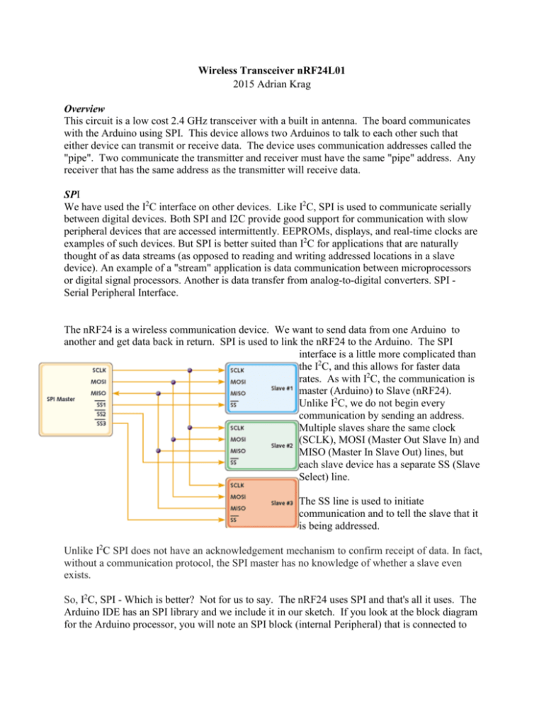
The nRF24 is a wireless communication device. We want to send data from one Arduino to
another and get data back in return. SPI is used to link the nRF24 to the Arduino. The SPI
interface is a little more complicated than
the I2C, and this allows for faster data
rates. As with I2C, the communication is
master (Arduino) to Slave (nRF24).
Unlike I2C, we do not begin every
communication by sending an address.
Multiple slaves share the same clock
(SCLK), MOSI (Master Out Slave In) and
MISO (Master In Slave Out) lines, but
each slave device has a separate SS (Slave
Select) line.
The SS line is used to initiate
communication and to tell the slave that it
is being addressed.
Unlike I2C SPI does not have an acknowledgement mechanism to confirm receipt of data. In fact,
without a communication protocol, the SPI master has no knowledge of whether a slave even
exists.
So, I2C, SPI - Which is better? Not for us to say. The nRF24 uses SPI and that's all it uses. The
Arduino IDE has an SPI library and we include it in our sketch. If you look at the block diagram
for the Arduino processor, you will note an SPI block (internal Peripheral) that is connected to
port B, and that Port B, pin 2 (D10) is capable of the SS function, Port B, pin 3 (D11) is capable
of MOSI function, Port B pin 4 (D12) is the MISO function and Port B pin 5 (D13) is SCLK.
nRF24L01
Let's look at the nRF24 - this device is built around the Nordic nRF24L01 integrated circuit
which is a wireless transceiver chip. http://www.nordicsemi.com/eng/Products/2.4GHzRF/nRF24L01P Our product integrates an oscillator, voltage regulator, and zig-zag antenna, all
on a board with pins that can connect to an Arduino. The part is cheap, because the Nordic chip
is used in lots of things so they make lots of them and this brings the cost way down.
The part has 8 pins on the
board, 6 of which are
essential. 7 of which we are
going to use.
Note on the back of the
chips is a pin marked CSN This is the SS pin. CE is a
Chip Enable pin that allows
the Arduino to shut down the
Nordic chip to save power.
Of course we need power (VCC = 3.3 Volts). The Nordic chips does not run on 5 volts so you
need to connect to the 3.3 Volt Arduino pin. The SPI pins are 5 volt tolerant so it won't hurt if
you use normal digital outputs, but DON'T CONNECT VCC to 5 VOLTS.
1 - GND
2 - VCC 3.3V !!! NOT 5V
3 - CE to Arduino pin 8
4 - CSN to Arduino pin 10
5 - SCK to Arduino pin 13
6 - MOSI to Arduino pin 11
7 - MISO to Arduino pin 12
8 - UNUSED */
Connect the pins 1 to 7 on the nRF24 to the appropriate Arduino Pins.
Transmitter Program
Let's look at a program - As, mentioned, we will need the SPI library and we will need the
nRF24L01 library.
/*-----( Import needed libraries )-----*/
#include <SPI.h>
#include <nRF24L01.h>
#include <RF24.h>
Get these libraries from the https://github.com/maniacbug/RF24 or write to me and I'll send you
the zip file. Install the library - Note, it has both the RF24.h and nRFL01.h in the same file.
To use the Easy install, you will need to rename the zip file. nRF24-master.zip will download,
but you need to delete the -master from the name or the Arduino easy installer will not know
what to do with it.
/*-----( Declare Constants and Pin Numbers )-----*/
#define CE_PIN 8
#define CSN_PIN 10
These are just definitions - that help in remembering where we put stuff.
RF24 radio(CE_PIN, CSN_PIN); // Create a Radio
This line is the constructor - it creates a copy of the RF24 class - in this case called radio - just a
name. Could be anything. The constructor requires 2 parameters - need to know which pin is
the CE (Chip Enable pin) and which pin is the CSN (SS Slave Select Pin).
Now that we have the RF24 class (called radio in our program) we can use all the functions.
RF24 (uint8_t _cepin, uint8_t _cspin)
Constructor.
void
begin (void)
Begin operation of the chip.
void
startListening (void)
Start listening on the pipes opened for reading.
void
stopListening (void)
Stop listening for incoming messages.
bool
write (const void *buf, uint8_t len)
Write to the open writing pipe.
bool
available (void)
Test whether there are bytes available to be read.
bool
read (void *buf, uint8_t len)
Read the payload.
void
openWritingPipe (uint64_t address)
Open a pipe for writing.
void
openReadingPipe (uint8_t number, uint64_t address)
Open a pipe for reading.
We are going to use all of these in the transmit and receive programs. More information can be
found at http://maniacbug.github.io/RF24/classRF24.html
const uint64_t pipe = 0xE7E7E7E7E7LL; // Define the transmit pipe
Now things get interesting. The nRF24L01 is a 2.4Ghz transceiver. That means that the data is
transmitted as variations in frequency around 2.4Ghz. Just like an FM radio, there are lots of
channels, each on a slightly different frequency. To specify a channel, we need to give the
program a number - Specifically a 40 bit number. Unfortunately, there aren't any 40 bit numbers
(uint40_t) in the Arduino. There are 64 bit numbers (uint64_t) in the C language, but the
Atmel328 processor is an 8 bit device so it can't handle numbers that big without some special
code instructions.
We need to specify a 40 bit number - Above we decide to use E7E7E7E7 - This is a Hex number
the 0x in front tells us we are dealing with hex - Each letter and number is 4 bits - total 40. In
decimal, this number is 3,890,735,079. Actually, looking at the decimal equivalent, I can't tell if
it's 40 bits or not.
As mentioned above, the Arduino needs special programs to deal with numbers this big. The LL
at the end tells the compiler that we will need the extra processing routines.
This is called the pipe - the pipe is the channel that we will be transmitting on and the same
channel that we will be receiving. If you don't like 0xE7E7E7E7 - Choose something else
0x9B2438AD for example - however, it's important that whatever you pick for a transmit pipe,
you must use the same for the receiver.
int Cmd[4]; // 4 element array holding the 4 command integers
The SPI interface is used to transmit data, usually large amounts of data. This line defines an
integer array of variables, 4 of them to be exact. They are Cmd[0], Cmd[1], Cmd[2] and Cmd[3].
An array of variables is similar to defining individual variables - same rules apply - must start
with a letter - no spaces or weird characters. Must specify a type - in this case integers - Could
have use char or float. Arrays have the advantage that you can pick the variable you want by
using another variable as the index:
for (int i = 0; i < 4; i++) // this code will set all 4 variables to be 15.
Cmd[i] = 15;
// arrays use indirect addressing and this is a powerful capability
void setup()
{
Serial.begin(9600);
radio.begin();
radio.openWritingPipe(pipe);
}
That's all the global things now we are into the setup() procedure. Serial.begin(9600); opens the
Serial monitor - This is the begin() that is part of the Serial class. We also have a begin() that is
in the newly created radio class. Finally we are going to use a new function openWritingPipe().
This function call activates the channel that we specified with the 40 bit pipe variable.
void Snd4(int C0, int C1, int C2, int C3)
{
Cmd[0] = C0; Cmd[1] = C1; Cmd[2] = C2; Cmd[3] = C3;
radio.write( Cmd, sizeof(Cmd) );
}
In this program I created a separate function to load the array and send the data. I called it Snd4
and it has 4 variables, the 4 values to fill the Cmd Array.
In this function, I use the write() command in the radio class to send the 4 integers - note, that's 8
bytes. The write() function call requires 2 variables. The second is the number of bytes in the
array that we are sending. The program uses the sizeof() function to get the total number of
bytes to be sent.
An interesting thing about arrays - if you write Cmd[x], that means the value of that one variable.
However, if you just write Cmd - that means the address of where the start of the array is stored
in memory. The first variable required by the write() call is the address of where the data starts.
The write function sends bytes - it doesn't know if these are bytes that make up characters, or
integers or longs or doubles or floats. The nRF24 doesn’t care what the bytes are.
void loop() /****** LOOP: RUNS CONSTANTLY ******/
{
Snd4 (128, 128, 0, 0); // forward half Speed.
delay (1000);
Snd4 (200, 0, 0, 200); // hard Right swival
delay (1000);
Snd4 (0, 200, 200, 0); // hard Left swival
delay (1000);
Snd4 (0, 0, 200, 200); // Back up
delay (1000);
}
In the loop() program I send 4 integers, wait 1 second - Then 4 others - Nothing very exciting
here.
Let's look at the whole program:
/* http://arduino-info.wikispaces.com/Nrf24L01-2.4GHz-HowTo
1 - GND
2 - VCC 3.3V !!! NOT 5V
3 - CE to Arduino pin 8
4 - CSN to Arduino pin 10
5 - SCK to Arduino pin 13
6 - MOSI to Arduino pin 11
7 - MISO to Arduino pin 12
8 - UNUSED */
/*-----( Import needed libraries )-----*/
#include <SPI.h>
#include <nRF24L01.h>
#include <RF24.h>
/*-----( Declare Constants and Pin Numbers )-----*/
#define CE_PIN 8
#define CSN_PIN 10
const uint64_t pipe = 0xE7E7E7E7E7LL; // Define the transmit pipe
RF24 radio(CE_PIN, CSN_PIN); // Create a Radio
/*-----( Declare Variables )-----*/
int Cmd[4]; // 4 element array holding the 4 command integers
void setup() /****** SETUP: RUNS ONCE ******/
{
Serial.begin(9600);
radio.begin();
radio.openWritingPipe(pipe);
}//--(end setup )--void loop() /****** LOOP: RUNS CONSTANTLY ******/
{
Snd4 (128, 128, 0, 0); // forward half Speed.
delay (1000);
Snd4 (200, 0, 0, 200); // hard Right swival
delay (1000);
Snd4 (0, 200, 200, 0); // hard Left swival
delay (1000);
Snd4 (0, 0, 200, 200); // Back up
delay (1000);
}//--(end main loop )--void Snd4(int C0, int C1, int C2, int C3)
{
Cmd[0] = C0; Cmd[1] = C1; Cmd[2] = C2; Cmd[3] = C3;
radio.write( Cmd, sizeof(Cmd) );
}
This program was intended to control a robot - by sending the 4 integers need to control the 2
pins for the right motor and the 2 pins for the left motor.
Receiver Program
Much of the Receiver program is similar to the Transmitter program /* http://arduino-info.wikispaces.com/Nrf24L01-2.4GHz-HowTo
1 - GND
2 - VCC 3.3V !!! NOT 5V
3 - CE to Arduino pin 8
4 - CSN to Arduino pin 10
5 - SCK to Arduino pin 13
6 - MOSI to Arduino pin 11
7 - MISO to Arduino pin 12
8 - UNUSED
/*-----( Import needed libraries )-----*/
#include <SPI.h>
#include <nRF24L01.h>
#include <RF24.h>
/*-----( Declare Constants and Pin Numbers )-----*/
#define CE_PIN 8
#define CSN_PIN 10
The connections are identical, and we load the same libraries.
const uint64_t pipe = 0xE7E7E7E7E7LL; // Define the transmit pipe
Again, we define a 64 bit variable - called pipe in this case - This specifies the channel we will
be using. It must be the same number as the channel we specified in the transmitter program.
You can operate multiple transmitters and multiple receivers simultaneously if they are all on
different channels.
There is an interesting thing about the receiver channel - a receiver can receive data from up to 6
transmitters - that is it can have 6 open receive pipes simultaneously.
void setup() /****** SETUP: RUNS ONCE ******/
{
Serial.begin (9600);
radio.begin();
radio.openReadingPipe(1,pipe);
radio.startListening();;
}//--(end setup )--the setup() function is the similar, except, now we openReadingPipe() and startListening(). The
openReadingPipe() needs 2 parameters. The second is the pipe variable. A receiver can listen to
up to 6 transmitters simultaneously. The first variable is the pipe number, 0 to 5. Pipe 0 is the
same as the transmitting pipe, and pipes 1 to 5 should have the same first 32 bits (only the last 8
can be different.
The startListening() activates the receiver channel. There is also a stopListening() command that
closes the channel.
void loop() /****** LOOP: RUNS CONSTANTLY ******/
{
while(!radio.available());
radio.read(Cmd, sizeof(Cmd)); // Fetch the data payload
analogWrite (3, Cmd[0]);
analogWrite (5, Cmd[1]);
analogWrite (6, Cmd[2]);
analogWrite (9, Cmd[3]);
Serial.print (Cmd[0]);
Serial.print (" ");
Serial.print (Cmd[1]);
Serial.print (" ");
Serial.print (Cmd[2]);
Serial.print (" ");
Serial.println (Cmd[3]);
}//--(end main loop )--There are only a couple of interesting things in the loop() function. radio.available() is the same
as Serial.available() in that it returns the number of bytes in the buffer. The
while(!radio.available()); command waits until something is received and radio.available() is no
longer 0.
radio.read() needs 2 parameters. The first is the address of the start of an array to put the
received bytes in. The second is the maximum number of bytes that can be received. If you
know exactly how many bytes you are receiving. This is simple. If you don't, then things
become a bit more interesting.
/* http://arduino-info.wikispaces.com/Nrf24L01-2.4GHz-HowTo
1 - GND
2 - VCC 3.3V !!! NOT 5V
3 - CE to Arduino pin 8
4 - CSN to Arduino pin 10
5 - SCK to Arduino pin 13
6 - MOSI to Arduino pin 11
7 - MISO to Arduino pin 12
8 - UNUSED
/*-----( Import needed libraries )-----*/
#include <SPI.h>
#include <nRF24L01.h>
#include <RF24.h>
/*-----( Declare Constants and Pin Numbers )-----*/
#define CE_PIN 8
#define CSN_PIN 10
const uint64_t pipe = 0xE7E7E7E7E7LL; // Define the transmit pipe
RF24 radio(CE_PIN, CSN_PIN); // Create a Radio
int Cmd[4]; // 4 element array holding a 4 integer message
void setup() /****** SETUP: RUNS ONCE ******/
{
Serial.begin (9600);
radio.begin();
radio.openReadingPipe(1,pipe);
radio.startListening();;
}//--(end setup )--void loop() /****** LOOP: RUNS CONSTANTLY ******/
{
while(!radio.available());
radio.read(Cmd, sizeof(Cmd)); // Fetch the data payload
analogWrite (3, Cmd[0]);
analogWrite (5, Cmd[1]);
analogWrite (6, Cmd[2]);
analogWrite (9, Cmd[3]);
Serial.print (Cmd[0]);
Serial.print (" ");
Serial.print (Cmd[1]);
Serial.print (" ");
Serial.print (Cmd[2]);
Serial.print (" ");
Serial.println (Cmd[3]);
}//--(end main loop )--This is the whole program - I have loaded it and it worked. In this case I write the values to the
PWM pins to control motor speed and I also write them to the display.
Things that go wrong
It took me a couple tries to get this to work. Some of the libraries that I downloaded that were
supposed to be for this product didn't work. The reference above did work for me.
The nRF24L01 requires pretty clean 3.3V power. I had to put a 10uF cap across the power lined
to reduce the noise.
Wiring is critical - you have to get all 7 of the wires where they are supposed to be - If it doesn't
work, check that first.
Make sure your transmitter and receiver pipes are exactly the same - easy to make a mistake
there.
