Test (50 mL·h -1 )
advertisement
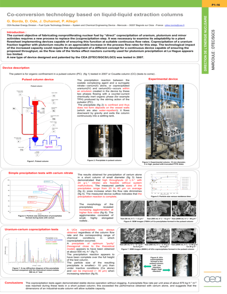
G. Borda, D. Ode, J. Duhamet, P. Allegri CEA Nuclear Energy Division – Fuel Cycle Technology Division – System and Chemical Engineering Device - Marcoule – 30207 Bagnols sur Cèze -France : gilles.borda@cea.fr Introduction : The current objective of fabricating nonproliferating nuclear fuel by “direct” coprecipitation of uranium, plutonium and minor actinides requires a new process to replace the (co)precipitation step. It was necessary to examine its adaptability to a plant flowsheet implementing devices capable of ensuring this function at suitable continuous flow rates. Coprecipitation of a uranium fraction together with plutonium results in an appreciable increase in the process flow rates for this step. The technological impact of the increased capacity could require the development of a different concept for a continuous device capable of ensuring the proposed throughput, as the flow rate of the Vortex effect reactors currently used for plutonium precipitation at La Hague appears too limited. A new type of device designed and patented by the CEA (DTEC/SGCS/LGCI) was tested in 2007. Device description The patent is for organic confinement in a pulsed column (PC) (fig 1) tested in 2007 or Couette column (CC) (tests to come) . Pulsed column device Pulsed column Aquous oxalic phase inlet Upper settler 2 12 Organic phase outlet 5 Main aquous nitrate phase inlet 8b Hydrophobic packing 13b 1 9b First aquous nitrate phase inlet Experimental device The precipitation reaction between the oxalate complexing agent and a surrogate nitrate—cerium(II) alone, or coprecipitated uranium(IV) and cerium(III)—occurs within an emulsion created in the device by these two phases flowing with a counter-current chemically inert organic phase (for example TPH) produced by the stirring action of the pulsator (PC) . The precipitate (fig 2) is confined and thus does not form deposits on the vessel walls (which are also water-repellent); it flows downward by gravity and exits the column continuously into a settling tank. Hydrophobic glass shaft 10b Organic phase inlet 3 Oxalic phase outlet 4 Recycled oxalic phase inlet 6 Lower settler 11b Oxalate precipitate 7 Figure 2. Precipitate in pulsed column Figure1. Pulsed column Figure 3. Experimental column, 15 mm diameter, 2 m high, packed with truncated PTFE disks Ce 50 mL.h-1 10% Ce 100 mL.h-1 Ce 200 mL.h-1 8% Ce 500 mL.h-1 6% Ce 1000 mL.h-1 The results obtained for precipitation of cerium alone in a short column of small diameter (fig 3) have demonstrated that high throughputs (2 L·h-1 with 24 g·L-1 nitrate) are feasible without system malfunctions. The measured particle sizes of the precipitates range from 20 to 40 µm on average (fig 4); sizes increase when the flow rate diminishes (fig 5). The measured device outflow indicates that the precipitation reaction is complete. 35 1,2 30 1 d43 for TPH = 2000 mL.h-1 d50 for TPH = 2000 mL.h-1 25 0,8 20 0,6 15 HNO3 and H2C2O4 (mol.L-1) 12% d43, d50 et d10 size of cerium precipitate versus residence time for liquid Size (µ) Simple precipitation tests with cerium nitrate d10 for TPH = 2000 mL.h-1 d43 for TPH = 500 mL.h-1 d50 for TPH = 500 mL.h-1 d10 for TPH = 500 mL.h-1 0,4 HNO3 concentration 10 H2C2O4 concentration 0,2 5 0 0,00 20,00 40,00 60,00 80,00 100,00 120,00 140,00 0 160,00 Residence time for liquid (s) Figure 5. Particle size versus residence time 4% Ce 1500 mL.h-1 2% Ce 2000 mL.h-1 0% 0,1 1 10 Size (µm) Figure 4. Particle size distribution of precipitates formed during tests with cerium Shocks Uranium-cerium coprecipitation tests 2 theta (degrees) Figure 7. X-ray diffraction diagram of the precipitate formed compared with the theoretical mixed oxalate. 500 mL.h-1 test 100 The morphology of the precipitates revealed increasing agglomeration at higher flow rates (fig 6). The agglomerates consisted of small, highly elongated rodlets . A UCe coprecipitate was always obtained regardless of the column flow rate and the corresponding range of chemical conditions in which coprecipitation occurred. A precipitate of optimum “purity” (hexagonal close to the theoretical model) appears to have been obtained at about 500 mL·h-1 (fig 7). The precipitation reaction appears to have been complete over the full height of the test column. The particle size of the resulting precipitate is smaller(~ 10 µm) than under inactive conditions (Ce alone) and can be improved (~ 30 µm) when increasing retention (fig 8). Test (50 mL·h-1) ~ 1.2 g·h-1 Test (500 mL·h-1) ~ 12 g·h-1 Test (2000 mL·h-1) ~ 48 g·h-1 Figure 6. SEM images (7500×) of Ce precipitates formed in the pulsed column Test (50 mL·h-1) ~ U 1 g·h-1 Test (500 mL·h-1) ~ U 10 g·h-1 Test (2000 mL·h-1) ~ U 40 g·h-1 Ce 0,5 g·h-1 Ce 5 g·h-1 Ce 20 g·h-1 Figure 7. SEM images (8000×) of UCe coprecipitates formed in the pulsed column Figure 8. UCe coprecipitates formed in the pulsed column: Left : low retention Right: High retention Conclusions The coprecipitation tests again demonstrated stable device operation without clogging. A precipitate flow rate per unit area of about 875 kg·h-1·m-2 was reached during these tests in a short pulsed column; this exceeded the performance obtained with cerium alone, and suggests that the dimensions of an industrial-scale column will allow suitable capacity. MARCOULE : DTEC/SGCS Co-conversion technology based on liquid-liquid extraction columns NUCLEAIRE DIRECTION NUCLEAIRE L’ENERGIE DEL’ENERGIE DIRECTIONDE P1-16
