ME3003 Electrical Distribution and Machines Model paper
advertisement
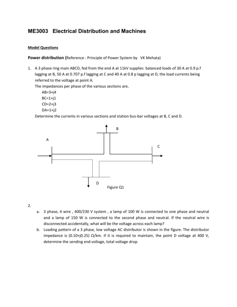
ME3003 Electrical Distribution and Machines Model Questions Power distribution (Reference : Principle of Power System by VK Mehata) 1. A 3 phase ring main ABCD, fed from the end A at 11kV supplies balanced loads of 30 A at 0.9 p.f lagging at B, 50 A at 0.707 p.f lagging at C and 40 A at 0.8 p lagging at D, the load currents being referred to the voltage at point A. The impedances per phase of the various sections are, AB=3+j4 BC=1+j1 CD=2+j3 DA=1+j2 Determine the currents in various sections and station bus-bar voltages at B, C and D. B A C D Figure Q1 2. a. 3 phase, 4 wire , 400/230 V system , a lamp of 100 W is connected to one phase and neutral and a lamp of 150 W is connected to the second phase and neutral. If the neutral wire is disconnected accidentally, what will be the voltage across each lamp? b. Loading pattern of a 3 phase, low voltage AC distributor is shown in the figure. The distributor impedance is (0.10+j0.25) Ω/km. if it is required to maintain, the point D voltage at 400 V, determine the sending end voltage, total voltage drop. A B 150 m 100 m C 200 m D 33kV/415V 200 kW, 100 kvar 300 kW at 0.87 p.f 100 kW at 0.98 p.f 3. a. A 2-wire d.c. distributor cable AB is 2 km long and supplies loads of 100A, 150A,200A and 50A situated 500 m, 1000 m, 1600 m and 2000 m from the feeding point A. Each conductor has a resistance of 0·01 Ω per 1000 m. Calculate the potential deference at each load point if a potential difference 300 V is maintained at point A b. A 2-wire d.c. distributor AB is 300 metres long. It is fed at point A. The various loads and their positions are given below At point distance from A (m) concentrated load(A) C D E F 40 100 150 250 30 40 100 50 If the maximum permissible voltage drop is not to exceed 10 V, find the cross-sectional area of the distributor. Take ρ = 1·78 × 10−8 Ωm. 4. a. A single phase motor connected to 400 V, 50 Hz supply takes 31·7A at a power factor of 0·7 lagging. Calculate the capacitance required in parallel with the motor to raise the power factor to 0·9 lagging. b. A factory takes a load of 200 kW at 0·85 p.f. lagging for 2500 hours per annum. The traiff is Rs. 400 per kVA plus Rs. 9 per kWh consumed. If the p.f. is improved to 0·9 lagging by means of capacitors costing Rs 420 per kVAR and having a power loss of 100 W per kVA, calculate the annual saving effected by their use. Allow 10% per annum for interest and depreciation. Wiring regulations and safety 5. a. What are the advantages and disadvantages of the various types of earthing systems? (Draw the labeled diagrams for each) b. What is the purpose of IEE wiring regulation c. What is the use of Maximum demand and diversity for an electrical installation d. What are methods of protections against direct contact (Basic protection) e. What are the method of protections against indirect contact (Fault protection) f. Explain the operation of a Residual Current Device g. What is the difference between RCCB and MCB h. What is an electric shock Transformers (Electrical Machines bimbhra and Electrical technology bl theraja vol 1) 6. a) What current flows in the transformer primary when it’s secondary open? What is its function and give its order of magnitude. b) A 200 kVA, 11 KV/400V, delta-star distribution transformer gave the following test results results, Open circuit test- 400 V, 9 A, 1.5 kW Short circuit test- 350 V, rated current, 2.1 kW Calculate the equivalent circuit parameters referred to the hv side and its efficacy at half full load of unity power factor 7. a) What are the two types of transformer cores are used? (use clear diagrams) b) An ideal transformer has an input voltage of 480 V. The output current and voltage are 10 A and 120 V. Determine the value of input current. c) A 15-kVA, 2400:240-V, 60 Hz transformer has the following equivalent circuit parameters: 𝑅1 = 2.5 Ω, 𝑅2 = 0.025 Ω, 𝑋1 = 7 Ω, 𝑋2 = 0.07 Ω, 𝑅𝑐 = 32 𝑘Ω, 𝑋𝑚 = 11.5 𝑘Ω If the transformer is supplying a 10 kW, 0.8 PF lagging load at rated voltage, calculate: (a) Input voltage (b) Input current, and (c) Input power factor Electrical machines (Electrical Machines bimbhra and Electrical technology bl theraja vol 1) DC Motors and generators 8. a. What is meant by armature reaction? b. A 460 V series motor runs at 500 rpm taking current of 40 A. calculate the speed and percentage change in torque if the load is reduced so that the motor is taking 30 A. Total resistance of the armature and field circuit is 0.8 Ω. Assume flux is proportional to the filed current c. A 220 V dc series motor is running at a speed of 800 rpm and draws 100 A. Calculate at what speed the motor will run when developing half the torque. Total resistance of the armature and filed is 0.1 Ω. Assume that the magnetic circuit is unsaturated. 9. d. A 250 V, dc shunt motor has an armature resistance of 0.5 Ω and a field resistance of 250 Ω. When driving a load of constant torque at 600 rpm, the armature current is 20 A. if it is desired to raise the speed from 600 to 800 rpm, what resistance should be inserted in the shunt field current? Assume that the magnetic circuit is unsaturated e. A 250 V shunt motor runs at rpm at no load and takes 8 A. The total armature and shunt field resistances are respectively o. 2 Ω and 250 Ω. Calculate the speed when loaded and taking 50 A. Assume the flux to be constant. Induction Motors 10. a. Discuss the starting methods for a 3 phase induction motor b. Give the difference between an induction motor and a transformer. c. A 12 pole, 3 phase alternator driven at 500 rpm supplies power to a 8 pole 3 phase induction motor. If slip of motor at full load is 3%, calculate the speed of the motor. d. A 3 phase induction motor has starting torque of 100% and a maximum torque of 200% of the full load torque. Find slip at maximum torque. Synchronous motors 11. a. Draw the per phase equivalent circuit of a cylindrical rot r generator and derive the basic power angel characteristic equation b. 100 MVA , 11 kV, 50 Hz cylindrical rotor generator delivers 60 MW and 25 MVAr at rated terminal voltage. Synchronous reactance of the machine is 1.2 pu. Find the internal EMF and load angle.


