ppt - Little Calumet River Basin Development Commission
advertisement
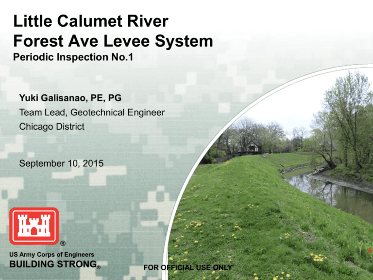
Little Calumet River Forest Ave Levee System Periodic Inspection No.1 Yuki Galisanao, PE, PG Team Lead, Geotechnical Engineer Chicago District September 10, 2015 US Army Corps of Engineers BUILDING STRONG® FOR OFFICIAL USE ONLY Agenda • System Description • Design Criteria Review • Inspection Findings • Conclusions & Recommendations FOR OFFICIAL USE ONLY 2 BUILDING STRONG® SYSTEM DESCRIPTION FOR OFFICIAL USE ONLY 3 BUILDING STRONG® FOR OFFICIAL USE ONLY 4 BUILDING STRONG® Summary Information • • Features Measurement Levee 2,000 LF Sheet Pile Wall 325 LF Concrete Block Wall 1,950 LF Gap Closures 9 Culverts 6 Check Valves 3 Pump Stations 2 Protected Area 55 acres This is part of a federally authorized and non-federally operated and maintained urban flood-protection project. It was non-federally constructed and incorporated into the project when the PCA was signed. The State Line Rd tieback was non-federally constructed and is waiting for approval under the Section 408 Permit process to be incorporated into the project. The overall Little Calumet River Project was authorized to a 200 year level of protection. The levee portion of the Forest Ave system was constructed to the 200 year. The State Line Rd tieback and the area between Hohman Ave and the NICTD Railroad does not quite provide a 200 year level of protection. Plans to achieve the 200 year level of protection will be completed at a later date and will include raising the State Line Rd Tieback and constructing floodwall in the neighboring Southmoor subdivision east of Hohman Ave. FOR OFFICIAL USE ONLY 5 BUILDING STRONG® Project Modifications • Permit 10-06 7258 Forest Ave Drainage o • Permit 11-02 Forest Ave Levee Repairs o • The work consisted of removing vegetation from the levee; repairing holes left in the levee from tree removal; drainage modifications that included replacing portions of culverts, adding manholes and check valves; and seeding. Construction occurred from October to December 2012. Permit 13-05 State Line Tieback o • The permit request consists of installing a perforated drain line along the toe of the levee and connecting to a catch basin and 8 inch PVC pipe that leads out to a storm inlet on the road. This request was submitted in response to was backflow of river water through a flap gate that caused interior flooding of a property behind the levee during the 2008 flood. The work consisted of constructing a semi-permanent concrete block wall with gaps along State Line Road up to the 100 year level of protection. The wall was not tied into the existing levee. Although the Local Sponsor did not receive approval for the permit, construction took place between Nov 2013 and Jun 2014. Permit 15-01 Forest Ave Manhole o The work consists of removing the pump in the manhole at Station 1+38.31, cleaning the pipes, abandoning the 2 inch PVC pipe by backfilling the pipes and manhole with flowable fill, removing the check valve, and then capping the manhole with clay and seed. FOR OFFICIAL USE ONLY 6 BUILDING STRONG® Foundation Geology FOR OFFICIAL USE ONLY 7 BUILDING STRONG® DESIGN CRITERIA REVIEW FOR OFFICIAL USE ONLY 8 BUILDING STRONG® Hydraulics Criteria Hydrologic Analysis of Interior Areas Guidance EM 1110-2-1413 (15 January 1987) EM 1110-2-1416 (15 October 1993) Applicable Yes Criteria Met Yes Yes Yes Channel Stability Assessment for Flood Control Projects EM 1110-2-1418 (31 October 1994) Yes Yes Hydraulic Design of Flood Control Channels Risk Based Analysis for Flood Damage Reduction Studies USACE Process for the National Flood Insurance Program Levee Evaluation (NFIP) EM 1110-2-1601 (30 June 1994) EM 1110-2-1619 (1 August 1996) EC 1110-2-6067 (31 August 2010) Yes Yes Yes Yes Yes Yes Risk Analysis for Flood Damage Reduction Studies Hydraulic Design for Local Flood Protection Projects ER 1105-2-101 (3 January 2006) ER 1110-2-1405 (30 September 1982) ETL 1110-2-299 (22 August 1986) River Hydraulics Overtopping of Flood Control Levees and Floodwalls FOR OFFICIAL USE ONLY Yes Yes Yes Yes Yes Yes 9 Comment An interior hydraulic analysis was performed for the Forest Avenue levee segment that conforms with the EM requirements Due to the complex hydraulics (flow splits, flat gradient) unsteady flow modeling was selected as the appropriate hydraulic analysis method A sediment analysis was provided in FDM 5 Volume 2 Appendix A pages A-23and A-24. There have been no significant changes to the channel in regard to the Forest Avenue Levee Adequate erosion protection (rip rap) design was included The 13 May 2010 memo includes a risk analysis consistent with the EM requirements The risk analysis included in the 13 May 2010 memo is consistent with the EC requirements. The Corps has not performed a full levee system evaluation in support of the NFIP for Forest Avenue/ State Line Levee. The risk analysis developed for the 13 May, 2010 memo is consistent with the requirements of the ER The unsteady flow model developed to evaluate the levee is of sufficient detail and complexity to evaluate the potential flood risk posed by Little Calumet River/Thorn Creek. A superiority analysis was performed that includes the Forest Avenue Levee segment. The superiority analysis assumes the Corps design with 200 year plus freeboard protection between the NICTD railroad and the stateline with overtopping of the Illinois levee at the state line. The portion between the NICTD railroad and Hohman Avenue was not constructed, but would likely overtop at about the same time as the state line tieback. The intent of the ETL would be satisfied, i.e. overtopping would occur in locations that would have a minimal probability of BUILDING STRONG ® catastrophic impacts Geotechnical Criteria Settlement Analysis Guidance EM 1110-1-1904 (30 September 1990) EM 1110-2-1901 (30 April 1993) EM 1110-2-1902 (31 October 2003) EM 1110-2-1908 (30 June 1995) Applicable Yes Criteria Met No Comment No design documentation available. Yes No No design documentation available. Yes No No design documentation available. Yes No The EM does not prescribe mandatory requirements, but does recommend an instrumentation plan be developed. No instrumentation is present at the project, and no instrumentation plan was available for review. EM 1110-2-1913 (30 April 2000) Yes No No N/A No design documentation available showing that the proper seepage, settlement, and stability analysis was conducted. Crest width is less than 10’, and there is no record of an inspection trench. No design documentation available. Yes No No design documentation available. Yes No No design documentation available. Yes No While the project lies in a low risk seismic zone, ER-1110-21806 still requires a seismic evaluation. No documentation regarding seismic investigations was available. Engineering and Design, Design ETL 1110-2-569 Guidance for Levee Underseepage (1 May 2005) Yes No No design documentation available. Evaluation of I-Walls Yes No No design documentation available. Seepage Analysis and Control for Dams Slope Stability Instrumentation of Embankment Dams and Levees Construction of Levees Design, Construction and Maintenance of Relief Wells Stability Analysis of Concrete Structures Retaining and Floodwalls EM 1110-2-1914 (29 May 1992) EM 1110-2-2100 (1 December 2005) EM 1110-2-2502 (29 September 1989) Earthquake Design and Evaluation ER 1110-2-1806 for Civil Works Projects (31 July 1995) ETL 1110-2-575 (1 Sep 2011) FOR OFFICIAL USE ONLY 10 BUILDING STRONG® Civil Criteria Standards and Procedures for Referencing Project Elevation Grades to Nationwide Vertical Datums Guidance EM 1110-2-6056 (31 December 2010) Applicable Yes Criteria Met No Comment Notes on provided drawings indicated NGVD29 and Little Calumet River Coordinate System. Design and Construction of Levees EM 1110-2-1913 (30 April 2000) Yes No No design documentation available. Conduits, Culverts, and Pipes EM 1110-2-2902 (31 March 1998 Change 1) ER 1110-2-8160 (1 March 2009) Yes No No design documentation available. Yes No Notes on provided drawings indicated NGVD29 and Little Calumet River Coordinate System. ETL 1110-2-571 (10 April 2009) Yes No No design documentation available. Policies for Referencing Project Elevation Grades to Nationwide Vertical Datums Guidelines for Landscape Planting and Vegetation Management at Levees, Floodwalls, Embankment Dams, and Appurtenant Structures FOR OFFICIAL USE ONLY 11 BUILDING STRONG® Structural Criteria Evaluation and Repair of Concrete Structures Structural Design of Concrete Lined flood Control Channels Stability Analysis of Concrete Structures Strength Design for Reinforced Concrete Hydraulic Structures Design of Hydraulic Steel Structures Retaining and Flood Walls Guidance EM 1110-2-2002 (30 June 1995) EM 1110-2-2007 (30 April 1995) EM 1110-2-2100 (1 December 2005) EM 1110-2-2104 (20 August 2003) EM 1110-2-2105 (31 May 1994) EM 1110-2-2502 (29 September 1989) Design of Sheet Pile Walls EM 1110-2-2504 (31 March 1994) Structural Design of Closure EM 1110-2-2705 Structures for Local Flood Control (31 March 1994) Protection Projects Design of Pile Foundations EM 1110-2-2906 (15 January 1991) Structural and Architectural EM 1110-2-3104 Design of Pumping Stations (30 June 1989) Inspection, Evaluation and Repair of Hydraulic Steel Structures Responsibility for Hydraulic Steel Structures Evaluation of I-Walls EM 1110-2-6054 (1 December 2001) ER 1110-2-8157 (31 January 1997) ETL 1110-2-575 (1 Sep 2011) FOR OFFICIAL USE ONLY Applicable No Criteria Met N/A No N/A Comment The criteria given in this manual is for maintenance purposes, not design. Not Applicable No N/A Not Applicable Yes Yes No N/A The pump station outfall structures were designed in accordance with this document. Not Applicable Yes Yes The block wall was evaluated for sliding per this EM and met the safety factors. The SSP structure acts as a seepage barrier and stability support to the levee embankment. However, this levee section is called a flood wall in some project documents. No N/A Not Applicable No N/A Not Applicable No N/A Not Applicable Yes Yes Concrete modifications to the existing pump stations were designed in accordance with this document. New pump stations also meet these criteria. No N/A Not Applicable No N/A Not Applicable No N/A Not Applicable 12 BUILDING STRONG® Mechanical/Electrical Criteria Guidance Applicable Criteria Met Comment General Principles of Pumping Station Design and Layout EM 1110-2-3102 (February 1995) Yes No Discharge chamber at Forest Avenue pump station is not to the protection elevation. 7.4.b. Mechanical and Electrical Design of Pumping Stations EM 1110-2-3105 (August 1994) Yes No No documentation FOR OFFICIAL USE ONLY 13 BUILDING STRONG® INSPECTION FINDINGS FOR OFFICIAL USE ONLY 14 BUILDING STRONG® Preliminary Segment/System Rating Segment / System Rating Forest Ave Acceptable All items or components are rated as ACCEPTABLE Minimally Acceptable Minimally Acceptable One or more items are rated as MINIMALLY ACCEPTABLE or one or more items are rated as UNACCEPTABLE and an engineering determination concludes that the Unacceptable items would not prevent the segment / system from performing as intended during the next flood event. Unacceptable One or more items are rated as UNACCEPTABLE and would prevent the segment / system from performing as intended, or a serious deficiency noted in past inspections (which had previously resulted in a minimally acceptable system rating) has not been corrected within the established timeframe, not to exceed two years. Rehabilitation Program Status Rehabilitation Program Status FOR OFFICIAL USE ONLY Active 15 BUILDING STRONG® Field Inspection Date of Inspection – May 4, 2015 Levee Team: • Yuki Galisanao – USACE Lead • John Groboski – USACE Civil • Adam Karr – USACE GIS • Tina Kowitz – USACE Geotechnical • Erin Maloney – USAC Hydraulics • Andy Wadysz – USACE Structural • Dan Repay – LCRBDC • Mark Gordish - City of Hammond Pump Station Team: • Ernie Go – USACE Electrical • Robert Sezonov – USACE Mechanical • Ricky Wilcox – Hammond Sanitary District FOR OFFICIAL USE ONLY 16 BUILDING STRONG® Deficiency Map FOR OFFICIAL USE ONLY 17 BUILDING STRONG® Individual Item / Component Rating Definition Acceptable Minimally Acceptable Unacceptable The inspected item is in satisfactory condition, with no deficiencies, and will function as intended during the next flood event. The inspected item has one or more minor deficiencies that need to be corrected. The minor deficiency or deficiencies will not seriously impair the functioning of the item as intended during the next flood event. The inspected item has one or more serious deficiencies that need to be corrected. The serious deficiency or deficiencies will seriously impair the functioning of the item as intended during the next flood event. FOR OFFICIAL USE ONLY 18 BUILDING STRONG® General Items Rated Item 1. 2. 3. Operations and Maintenance Manuals Emergency Supplies and Equipment Flood Preparedness and Training FOR OFFICIAL USE ONLY Rating Comments M Forest Ave Levee System O&M Manual to be developed. It was identified as a separate system from the Hammond Levee. Manuals maintained by the City Engineering Department at City Hall and relevant copies distributed to appropriate internal agencies. A City of Hammond has ready inventory of flood fighting supplies and equipment. Primary resources available through public works department, but also can be supplemented by other city departments. Street Dept Public Works facility at 601 Conkey maintains pay loader, concrete blocks, portable welders, 69 pallets (100/pallet) of shrinkwrapped sandbags last checked 1-2 years ago, 2 forklifts, 1000 empty sandbags, 4 pallets of empty sandbags, and visqueen. Borrow source is Krooswyk. Hammond manually fills sandbags or uses a salt spreader to fill large quantities of bags. M Forest Ave Levee System flood response plan still to be developed. It was identified as a separate system from the Hammond Levee. Hammond uses reverse 911 and WJLB station to relay information. Public Works also uses frequency radios with the police and fire departments. Evacuation areas include City Hall, Civic Center, Jean Shepherd Community Center, Armory, Purdue University Calumet, Area Career Center. Fire Department has rescue boats. Specific features will need to be developed such as implementation of action levels for levee patrols, flood fighting, road closures, etc. A levee system Flood Warning Handbook is recommended to be prepared. Response action levels should be referenced to existing USGS River Gages at Hohman Ave. 19 BUILDING STRONG® Levee Embankment Rating Number of Deficiencies Minimally Acceptable 4 2. Sod Cover Acceptable 0 3. Encroachments Acceptable 0 Not Applicable - 5. Slope Stability Acceptable 0 6. Erosion / Bank Caving Acceptable 0 7. Settlement Acceptable 0 8. Depressions / Rutting Acceptable 0 9. Cracking Acceptable 0 Minimally Acceptable 2 11. Culverts / Discharge Pipes Acceptable 0 12. Riprap Revetments & Bank Protection Acceptable 0 13. Revetments other than Riprap Acceptable 0 Not Applicable - Acceptable 0 Rated Item 1. Unwanted Vegetation Growth 4. Closure Structures 10. Animal Control 14. Underseepage Relief Wells / Toe Drainage System 15. Seepage FOR OFFICIAL USE ONLY 20 BUILDING STRONG® Levee Embankment Unwanted Vegetation FOR OFFICIAL USE ONLY 21 BUILDING STRONG® Levee Embankment Animal Control FOR OFFICIAL USE ONLY 22 BUILDING STRONG® Floodwalls Rating Number of Deficiencies 1. Unwanted Vegetation Growth Minimally Acceptable 1 2. Encroachments Minimally Acceptable 1 3. Closure Structures Acceptable 0 4. Concrete Surfaces Acceptable 12 Minimally Acceptable 3 Acceptable 0 Minimally Acceptable 3 Not Applicable - Acceptable 0 Rated Item 5. Tilting, Sliding or Settlement of Concrete Structures 6. Foundation of Concrete Structures 7. Monolith Joints 8. Underseepage Relief Wells / Toe Drainage Systems 9. Seepage FOR OFFICIAL USE ONLY 23 BUILDING STRONG® Floodwalls Unwanted Vegetation and Encroachments FOR OFFICIAL USE ONLY 24 BUILDING STRONG® Floodwalls Concrete Surfaces FOR OFFICIAL USE ONLY 25 BUILDING STRONG® Floodwalls Tilting, Sliding or Settlement of Concrete Structures FOR OFFICIAL USE ONLY 26 BUILDING STRONG® Floodwalls Monolith Joints FOR OFFICIAL USE ONLY 27 BUILDING STRONG® Interior Drainage Rating Number of Deficiencies Minimally Acceptable 2 2. Encroachments Acceptable 0 3. Ponding Areas Not Applicable - 4. Fencing and Gates Not Applicable - 5. Concrete Surfaces Minimally Acceptable 1 6. Tilting, Sliding, or Settlement of Concrete and Sheet Pile Structures Acceptable 0 7. Foundation of Concrete Structures Acceptable 0 8. Monolith Joints Acceptable 0 9. Culverts / Discharge Pipes Acceptable 0 Not Applicable - 11. Flap Gates / Flap Valves / Pinch Valves Acceptable 0 12. Trash Racks Acceptable 0 13. Other Metallic Items Acceptable 0 14. Riprap Revetments of Inlet/ Discharge Areas Acceptable 0 Not Applicable - Rated Item 1. Vegetations and Obstructions 10. Sluice / Slide Gates 15. Revetments other than Riprap FOR OFFICIAL USE ONLY 28 BUILDING STRONG® Interior Drainage Vegetation and Obstructions FOR OFFICIAL USE ONLY 29 BUILDING STRONG® Interior Drainage Concrete Surfaces FOR OFFICIAL USE ONLY 30 BUILDING STRONG® Pump Stations Rating Number of Deficiencies 1. Pump Stations Operating, Maintenance, Training, & Inspection Reports Acceptable 0 2. Pump Station Operations and Maintenance Equipment Manuals Acceptable 0 3. Safety Compliance Acceptable 0 4. Communications Acceptable 0 5. Plant Building Acceptable 0 6. Fencing and Gates Acceptable 0 7. Pumps Acceptable 0 8. Motors, Engines, Fans, Gear Reducers, Back Stop Devices, etc. Acceptable 0 9. Sumps / Wet well Acceptable 0 Not Applicable - Minimally Acceptable 1 Not Applicable - 13. Power Source Acceptable 0 14. Electrical Systems Acceptable 0 15. Megger Testing on Pump Motors and Critical Power Cables Acceptable 0 16. Enclosures, Panels, Conduit and Ducts Acceptable 0 17. Intake and Discharge Pipelines Acceptable 0 18. Sluice / Slide Gates Acceptable 0 19. Flap Gates / Flap Valves / Pinch Valves Acceptable 0 Not Applicable - Rated Item 10. Mechanical Operating Trash Rakes 11. Non-Mechanical Trash Racks 12. Fuel System for Pump Engines 20. Cranes 21. Other Metallic Items 31 FOR OFFICIAL USE ONLY Acceptable BUILDING 0 STRONG ® Pump Stations Non-Mechanical Trash Racks FOR OFFICIAL USE ONLY 32 BUILDING STRONG® CONCLUSIONS & RECOMMENDATIONS FOR OFFICIAL USE ONLY 33 BUILDING STRONG® Design Recommendations FOR OFFICIAL USE ONLY 34 BUILDING STRONG® Design Recommendations Geotechnical • Perform a slope stability analysis to verify that the current levee condition, especially since the dimensions do not meet Corps standards. • A seepage analysis should be performed for the levee since there is no record of an inspection trench. A seepage analysis should also be performed for the tieback wall. • • Perform settlement calculations and seismic analysis. Perform a subsurface exploration approximately every 1,000 feet, consisting of an exploration at the riverside toe, at the landside toe, and a deep exploration at the levee crest. Civil • Perform a subsurface investigation to verify levee material. Structural • Provide the design analysis for the sheet pile wall. Mechanical • The design analysis, plans, specifications, and equipment data should be provided for the South Hohman Pump Station. FOR OFFICIAL USE ONLY 35 BUILDING STRONG® Inspection Recommendations FOR OFFICIAL USE ONLY 36 BUILDING STRONG® Item Levee Embankments Floodwalls Interior Drainage System Pump Stations Rated Item Rating Recommendations 1. Unwanted Vegetation M Remove trees on the levee and at the toe. Mow and maintain tall grass. 10. Animal Control M Fill open burrows. 1. Unwanted Vegetation Growth M Remove trees from next to sheet pile wall. 2. Encroachments M Remove debris from next to sheet pile wall. 5. Tilting, Sliding or Settlement of Concrete Structures M Repair sheetpile cap. 7. Monolith Joints M Caulk gaps in block wall. 1. Vegetation and Obstructions M Clear silt and vegetation from outlet. 5. Concrete Surfaces M Cracks on the headwall should be sealed and monitored for changes / deterioration. 11. Non-Mechanical Trash Racks M Clean debris FOR OFFICIAL USE ONLY 37 BUILDING STRONG®
