Final Spring Presentation - FAMU
advertisement
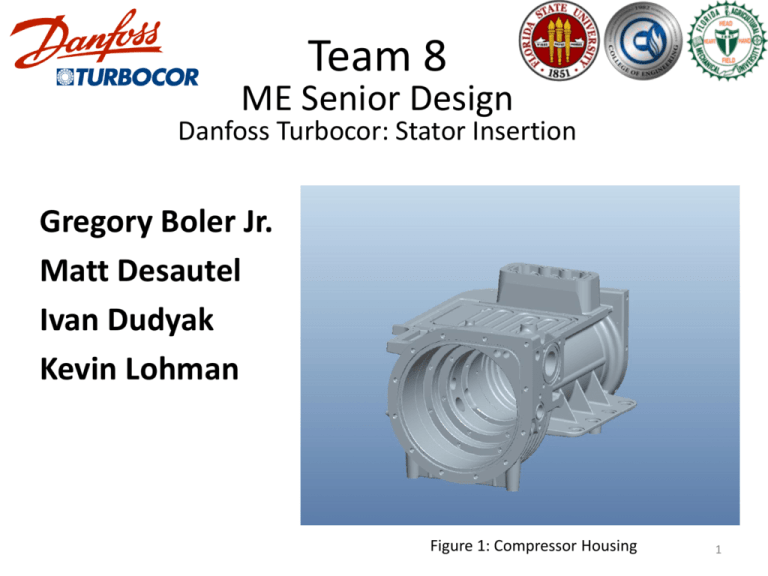
Team 8 ME Senior Design Danfoss Turbocor: Stator Insertion Gregory Boler Jr. Matt Desautel Ivan Dudyak Kevin Lohman Figure 1: Compressor Housing 1 Overview • • • • • • • • • • • • Danfoss Turbocor Background/Introduction Product Specification Design Approach Initial Expansion Calculations Experiment 1: Verifying Linear Expansion Concept Generation/Selection Heat Transfer Calculations Experiment 2: Proof of Concept Testing Design Details Cost Analysis Final Prototype Pictures Acknowledgments 2 Cutting Edge Compressors •Outstanding Efficiency •Totally oil-free operation •Extended life with minimal scheduled maintenance •Onboard digital controls and electronics •Exceptionally quiet operation •Compact Figure 2: Turbocor Compressor •Environmentally responsive 3 Introduction • Background – Heating of an aluminum housing to allow thermal expansion of the material – Once expanded a stator is inserted into the housing – The housing cools in ambient conditions locking the stator in place through an interference fit 4 Product Specification • Current method – Large oven requiring extensive floor space – Lengthy heating time ~ 45 minutes – High final temperature ~ 300°F – Four units per cycle – Long cooling time before the technicians can continue assembly is approximatly 60 minutes Figure 3: Current Oven 5 Product Specification • Current method – Stator inserted at a secondary station after heating cycle – Precise position required for pneumatic actuator – Additional floor space required for the secondary station Figure 4: Stator Insertion Station 6 Product Specification • Engineering Requirements – Reduced heating time, < 10 min. – Lower final temperature – Smaller size – Thermal expansion must allow for 60 microns clearance at maximum material conditions – Method for aligning stator and housing for thermocouple insertion 7 Problem Specification Preliminary thermal expansion calculations to determine the housing temperature to reach the desired clearance Experimental measurements of housing expansion in a thermal chamber Calculation of heat input needed to achieve the desired temperature using hot air Design concept and component selection based on analysis Design Approach Construction of heating unit proof of concept Final design and prototype of heating unit Experimental testing and design adjustment Final Product Evaluation 8 Initial Expansion Calculations • Sliding fit at maximum material condition 60 microns clearance Linear Expansion Equation 60.5 μm 61 °C 0 μm 45.5 °C Figure 5: Linear Expansion Relationship 9 Experiment 1: Verifying Linear Expansion Steps: 1. Heat housing 2. Take diameter measurements at various temperatures 3. Plot experimental data versus theoretical data 4. Data analysis Figure 6: Experiment 1 Figure 7: Bore Gauge (http://www.fvfowler.com) 10 Where to measure? Linear expansion equation Dimensionless linear expansion Figure 8: Compressor Housing Cross-Section 11 Non-Dimensional Linear expansion 0.003 0.0025 ΔL/L₀ 0.002 Theoretical 0.0015 Experimental 0.001 0.0005 0 0 0.0005 0.001 0.0015 0.002 0.0025 0.003 α*(T₂-T₁) Figure 9: Experiment 1 Data Analysis 12 Concept Decision Matrix Concept Selection Convective Oven Oil bath Internal Resistive Induction Heating Selection Criteria Weight Rating Weight Score Rating Weight Rating Score Weight Score Rating Weight Score Performance 30% 4 1.2 5 1.5 3 0.9 3 0.9 Complexity 20% 4 0.8 3 0.6 2 0.4 2 0.4 Size 20% 3 0.6 2 0.4 4 0.8 3 0.6 Durability 15% 3 0.45 4 0.6 1 0.15 2 0.3 Cost 10% 2 0.2 2 0.2 3 0.3 3 0.3 User Friendly 5% 3 0.15 1 0.05 3 0.15 3 0.15 Total 3.4 3.35 2.7 2.65 Ranking 1 2 3 4 13 Concept Decision Matrix Concept Selection Convective Oven Oil bath Internal Resistive Induction Heating Selection Criteria Weight Rating Weight Score Rating Weight Rating Score Weight Score Rating Weight Score Performance 30% 4 1.2 5 1.5 3 0.9 3 0.9 Complexity 20% 4 0.8 3 0.6 2 0.4 2 0.4 Size 20% 3 0.6 2 0.4 4 0.8 3 0.6 Durability 15% 3 0.45 4 0.6 1 0.15 2 0.3 Cost 10% 2 0.2 2 0.2 3 0.3 3 0.3 User Friendly 5% 3 0.15 1 0.05 3 0.15 3 0.15 Total 3.4 3.35 2.7 2.65 Ranking 1 2 3 4 14 Convection Heating Design Key Components •Insulated hood •Heater •Insulated heater enclosure •External blower •Housing alignment table Figure 10: Provisional Design 15 Q loss 1 Q21 Heat Transfer Analysis W Heat input to system 2 from heater Q21 2 Heat transferred from system 2 to system 1 Q loss W Figure 11: Heat Transfer System Heat lost from system 2 to outside environment 16 System 1 First Law System 1 1 Q21 System 2 Q loss First Law System 2 Q21 2 W Figure 12: Heat Transfer Systems 17 Coupled System of Ordinary Differential Equations Initial Conditions MATLAB MSC 5600 watt electric portable heater Figure 13: Electric Heater (http://www.mscdirect.com) 85 °C (60 °C Change) 11 min Figure 12: System Temperature vs. Time 18 Experiment 2: Proof of Concept Testing Thermocouple Housing Insulation Heater Blower Figure 14: Experiment 2 Setup 19 Experiment 2: Proof of Concept Data Housing Temperature Change (ΔT) Change in Housing Temperature vs. Time 90.00 80.00 70.00 60.00 50.00 40.00 30.00 20.00 10.00 0.00 0 2 4 6 8 10 12 14 16 Time (min) Theoretical Housing Temperature Change Run 1 Run 2 Run 3 Run 4 Figure 15: Experiment 2 Data 20 Experiment 2: Proof of Concept Data Change in Housing Temperature vs. Time Housing Temperature Change (ΔT) 90.00 80.00 70.00 60.00 50.00 40.00 30.00 20.00 10.00 0.00 0 -10.00 2 4 6 8 10 12 14 16 Time (min) Theoretical Housing Temperature Change Experimental Average Housing Temperature Change (2 Standard Deviations Error) Figure 16: Experiment 2 Average Data 21 Final Design Structure •Main structure assembled utilizing 80/20 •Hood lowers and closes using sliding Teflon bearings •Lid slides open and closed utilizing Teflon bearings •Pneumatic actuator utilizing expanding mandrel to place stator Pneumatic Actuator Lid Hood Main Structure Figure 17: Main Structure 22 Final Design Stator Alignment Key Features: •Pins to locate stator alignment ring •Pin to align stator to stator alignment ring •Pins to locate housing •Spring loaded mechanism to move housing into position •Slots to allow air circulation 23 Final Design: Stator Inserter Figure 18: Expanding Mandrel Temporary Stator Inserter No Rotation of Stator •Allows stator insertion by hand •Temporary system due to time constraints Figure 19: Temporary Stator insertion Cost Analysis Table 1: Convection Heater Cost Analysis Unit Price QTY Total Price ($) ($) Part Description Supplier Electric Heater 5600W 100 CFM MSC 138.09 1 138.09 Blower 515 CFM MSC 249.95 1 249.95 Steel Plate Plate for base MSC 320.00 1 320.0 Table Lever Parts Spring, Sleeve Bearing, Slider Pin, Drill Rod MSC N/A 12 37.16 Ultra Flex Hose 5' Length 4" ID MSC 74.24 1 74.24 80/20 Extrusion 25 Series Mono Slot Bar 6m AES 63.40 N/A 760.80 80/20 Hardware Misc. Hardware AES N/A N/A 1878.85 Aluminum Sheet Metal Alloy 6061 MSC 43.57 1 43.57 Total 3502.66 Final Prototype Pictures Figure 20: Final Prototype 27 Acknowledgements Turbocor Rob Parsons Dr. Lin Sun Kevin Gehrke Famu/FSU College of Engineering Dr. Juan C. Ordóñez Dr. Kareem Ahmed Dr. Rob Hovsapian Dr. Srinivas Kosaraju 28 Questions? 29


