Space Shuttle Structures
advertisement
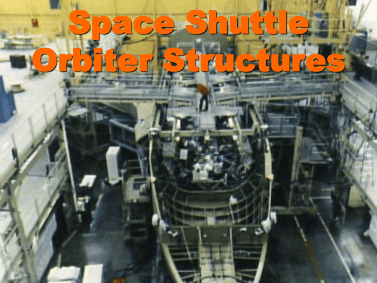
Space Shuttle Orbiter Structures Orbiter Structures Similarities of the Space Shuttle Orbiter to conventional commercial transport aircraft are numerous High-lift main wings Vertical stabilizer and rudder Tubular/cylindrical fuselage Horizontal (runway) landing on main and nose wheel landing gear Aluminum alloy primary structure Monocoque outer skin structure (skin and stringer) add to strength of inner members Similar fabrication methods Hydraulic aero surfaces used for flight control in the atmosphere Orbiter Structures Differences between the Space Shuttle Orbiter and conventional commercial transport aircraft are also numerous No rear horizontal wing or forward canard for pitch control Orbiter pitch control with bodyflap, split elevons, and speed brake Top-opening cargo bay Insulation over entire outer surface Hypersonic flight control using gas jets Some of the subsonic and supersonic flight is controlled with aero surfaces Unpowered flight through the atmosphere during reentry and landing Orbiter Structures Orbiter Structures Basic Orbiter specs Length 37.2 m (122') Height 7.4 m (57') Wingspan 3.8 m (78') Launch weight (approx) 104,545 kg (230,000 lb) Cargo bay capacity 4.6 m x 18.3 m (15' x 60') 27,273 kg (60,000 lb) (max, 28.5o inclination) Primary structure Aluminum alloys, steel alloys, titanium, and composites Design life 100 flights Orbiter Structures Primary structures The Orbiter is comprised of nine major sections that house the systems, payloads and crews, covered by thermal protection insulation. 1. Forward fuselage 2. Wings 3. Midfuselage 4. Payload bay doors 5. Aft fuselage 6. Forward Reaction Control System 7. Vertical tail 8. OMS/RCS System 9. Body flap Orbiter Primary Structures Orbiter Structures Orbiter constructed as three fuselage sections Forward fuselage Mid fuselage Aft fuselage Orbiter Structures Orbiter Structures – Forward Fuselage Orbiter Structures Forward fuselage Double shell pressurized structure Composed of Al 2219 alloy Pressure vessel serves as crew compartment Orbiter Structures Orbiter Structures – Forward Fuselage (interior) Orbiter Structures – Forward Fuselage Orbiter Structures Forward fuselage Initially covered mostly with high-temperature reusable surface insulation (HRSI) with the exception of the nose cap and wing leading edges Much of the HRSI was replaced with Advanced Flexible Reusable Surface Insulation (AFRSI) Nose cap Composed of reinforced carbon-carbon (RCC) Primary flight operations are conducted in upper flight deck and lower mid deck Access hatches for the airlock/docking tunnel and side hatch are located on the mid deck Contains 12 window sets that are made up of triple-pane silica glass Orbiter Structures – Forward Flight Deck Orbiter Structures - Wings Orbiter Structures Wings The Orbiter wings structure consists of a single pair of main wings attached to the mid fuselage assembly Composed of aluminum alloy using a skin-stringer design with a double-delta shape for hypersonic-supersonicsubsonic flight stability Outboard section includes a leading-edge spar for mounting the RCC panels and insulation attachments Orbiter Structures - Wings Orbiter Structures – Simple Aircraft Wing Orbiter Structures Wings Trailing-edge spar provides a structural mount for the split elevon hinges and actuators Aluminum alloy honeycomb skin panels Split elevon configuration allows roll and pitch control, with yaw controlled by the rudder mounted on the vertical tail Complex thermal protection required because of gaps and moving surfaces Orbiter Structures – Control Surfaces Orbiter Structures Mid Fuselage Designed to carry the payload weight while providing a rigid structure to transfer loads form the main engines and SRBs to and from the Orbiter Designed also to eliminate torsional rotation between the aft and forward fuselage sections Aluminum alloy structure Dimensions are 60' in length and 17' in width Consists of 12 main frames and braces that also incorporate trusses and stringers for rigidity Orbiter Structures Orbiter Structures Mid Fuselage Longerons on the upper section add stiffness and provide a rigid frame for the payload bay doors Prevents any distortion that could keep the payload bay door from opening or closing Skin panels were machined and included wing gloves ahead of the sidewall sections attached to the wings on each side Landing gear support structures were placed on the aft sidewall section of the mid fuselage Orbiter Structures Payload bay doors Each payload door is composed of five graphite epoxy honeycomb panels with expansion joints for thermal gradients during the extreme temperatures in space and during reentry Two aft panels and two forward radiator panels on each door The two radiator panels on the forward half of the door that can be extended outward to increase the cooling efficiency Each of the 18.3 m (60') long doors are covered with surface insulation quilts Orbiter Structures Orbiter Structures Payload bay doors Two Freon cooling loops circulate independently through the radiator panels Additional radiator panels can be added to the payload bay doors if needed for additional cooling capacity The payload bay doors are opened and closed with a 16.8 m (55') torque shaft Positive position latches for the doors can be operated either manually or automatically Orbiter Structures Orbiter Structures – Aft Fuselage Orbiter Structures Aft Fuselage Orbiter aft fuselage houses the main propulsion system, the bulk of which are the three SSMEs and the propellant distribution manifold Houses the APU and hydraulic systems, the flash evaporators and the ammonia boiler Supports the OMS pods and the vertical tail on the upper section Structure is comprised of: SSME thrust structure Secondary internal structure Outer shell made of machined aluminum alloy that adds structural strength Orbiter Structures – Aft Fuselage Orbiter Structures Aft Fuselage Aft fuselage skin and structure also create a pressure seal that is vented with actuators for equalizing pressures during ascent and reentry Constructed from aluminum alloys Primary SSME thrust structure is constructed of titanium truss members Orbiter Structures – Aft Fuselage Orbiter Structures Aft Fuselage The upper, outboard section provides the attachment surface for the OMS pods Constructed from aluminum alloys Top section is the vertical stabilizer support frame Constructed of titanium Bottom aft section includes the body flap hinge points and actuators Orbiter Structures – Aft Fuselage Orbiter Structures Forward Reaction Control System Forward and aft RCS provides attitude control for pitch, roll, and yaw on the Orbiter Also furnishes minor translational control for docking and undocking and for ET separation FRCS consists of a structural frame for the thrusters, propellant tanks, and associated hardware including helium tanks to pressurize the propellant tanks Orbiter Structures – FRCS Module Orbiter Structures Forward Reaction Control System Forward and aft RCS provides attitude control for pitch, roll, and yaw on the Orbiter on orbit Augments control surfaces in aerodynamic flight Also furnishes minor translational control for docking and undocking and for ET separation FRCS consists of: Structural frame for the thrusters Propellant tanks Associated hardware including helium tanks to pressurize the propellant tanks Orbiter Structures – FRCS Module Orbiter Structures Vertical tail Vertical tail and rudder assembly provide yaw control and longitudinal stability Tail assembly is effective only in the low supersonic and subsonic regime Yaw control in hypersonic and high supersonic flight is provided by the RCS system Constructed of aluminum alloy skin, stringers, ribs, and spars Aluminum honeycomb skin on the lower trailing edge Vertical tail supports the rudder and speed brake assembly Orbiter Structures Vertical tail Surface including the rudder and speed brake is covered with thermal tiles and blankets, Thermal barrier and seals placed at the hinge and interface regions of the tail Split rudder configuration allows left and right deflection for yaw control Separates vertically for added drag to reduce speed - the speed brake Also used for additional pitch control during the energy management phase and approach for landing Orbiter Structures – Vertical Tail Orbiter Structures OMS/RCS system pods Two aerodynamic pods are placed on the Orbiters outboard aft fuselage to house the two OMS and smaller RCS engines Pods are constructed primarily of graphite epoxy composite honeycomb skin sections Aluminum alloy frames, braces and ribs Titanium and corrosion-resistant steel fittings used near the engines as stiffeners Orbiter Structures – OMS Pods Orbiter Structures OMS/RCS system pods Each OMS pod is independent and removable for maintenance operations Low-Temperature Reusable Surface Insulation tiles cover most of the exposed surface of the OMS/RCS pods Thermal barriers surround the OMS and RCS engines to protect the aft fuselage equipment Orbiter Structures – OMS Pods Orbiter Structures Body flap Body flap is an aerosurface that furnishes additional pitch control for the Orbiter's flight through the atmosphere Also used for load reduction during the Orbiter's ascent to orbit Also deflects hot airflow from entering the Space Shuttle Main Engines during reentry Orbiter Structures – Body Flap Orbiter Structures Body flap Constructed of aluminum alloy skin and stringer panels, ribs, and spars Powered by four hydraulic rotary actuators within the lower aft fuselage Entire surface covered with reusable insulation tiles, with heat seals and barriers used for protection of the joints and moving surfaces Orbiter Structures – Aero Surfaces Orbiter Structures – Aero Surfaces Orbiter Structures Mechanical Systems Orbiter Structures Purge, Vent & Drain System (PVDS) PVDS is designed to accommodate the pressure changes, and the buildup of hazardous gases and fluids during normal flight operations An array of purge, dilution, vent (passive and active) and drain mechanisms are built into many of the Orbiter's pressurized sections to moderate pressure changes, and evacuate, or dilute, accumulated gases and fluids In addition, a number of components (SSME e.g.) require an inert gas purge to remove propellants or hazardous gases/liquids Pressurized nitrogen and helium gas purge subsystems supply the gas flow for fluid and gas removal to space Air is also used for post-landing pressure equilibration in several sections of the Orbiter Orbiter Structures – Aero Surfaces Orbiter Structures Airlock Airlock module allows crew access to: Payload bay for extravehicular activity Pressurized transfer tunnel to onboard facilities such as the Space Lab module (no longer used) ISS access docking port Orbiter Structures Airlock Airlock interior is 170 cubic feet (4.81 m3) in volume Includes accommodations for two fully-suited astronauts Oxygen supply Air revitalization Water Electrical power Communications Lighting Orbiter Structures Airlock Structure includes two hatches – one on the Orbiter interior and the second in the payload bay Hatches have pressure locks and seals for airlock access through each hatch in both directions Airlock pressurization for EVA is controlled by an automated system to allow a low-pressure pure oxygen environment to prepare astronauts for EVA Orbiter Structures Airlock The Orbiter's Airlock Module can also be used as a hypobaric chamber in case of a depressurization accident and/or decompression sickness The Orbiter's airlock is located either in the mid deck within the crew compartment, or in the payload bay if sufficient room is available Orbiter Structures – Airlock Orbiter Structures Windows Orbiter contains as many as 13 window sets Located in the forward and aft flight decks (10) One in the crew side access hatch Two in the airlock Each window set except the payload bay observation windows is comprised of three panes Provide pressure containment, light transmission properties, and physical strength Outer pane is manufactured for hightemperature resistance Two inner panes attached to the crew cabin are manufactured for high differential pressure resistance Orbiter Structures Windows Observation windows are polished surface, optical quality glass Composed of aluminosilicate (inner and outer panes), and fused silica (middle) Coatings are used on the surfaces to reduce reflectivity and IR heat inflow (inner pane) and to maximize visible light transmission (inner and outer panes) Window shades and filters are provided to reduce unnecessary heat and light exposure Shades are provided for all windows Filters are supplied for the aft and overhead viewing windows Orbiter Structures – Windows Orbiter Structures Landing Gear Orbiter's landing gear system closely resembles a conventional aircraft tricycle gear configuration Employs a nose gear and two main gear Each landing gear mechanisms includes an extension assembly with a shock strut Orbiter Structures – Landing Gear Orbiter Structures Landing Gear Each gear includes a dual-wheel and tire assembly that is attached to high-performance brakes with anti-skid control Braking on the rear landing gear and steering on the nose gear is operated with triple-redundant hydraulic system controls The nose landing gear is located in the lower forward fuselage which is retracted forward and up into the lower forward fuselage Orbiter Structures Landing Gear Gear mechanism is enclosed by two insulated, heat seal doors that are covered on the outside with HRSI insulation tiles Deployment of the Orbiter's landing gear in flight is controlled by the hydraulic system under pilot command Emergency release of the gear is provided by pyrotechnic actuators that release a mechanical lock for each gear that can be activated one second after the pilot command is initiated Orbiter Structures Landing Gear The nose and main landing gear can be retracted only during ground operations Modifications and improvements include Stiffening the gear structure Increasing the axle thickness to reduce tire damage Larger carbon disk brakes and improved 34-ply rating (16 cord) tires Orbiter Structures Shuttle Remote Manipulator System (SRMS) Space Shuttle payload deployment and retrieval system (aka Canadarm-1) has the capability to transfer payloads from the Orbiter's cargo bay to free-flight, or to grasp and transfer payloads from free-flight and return them to the cargo bay for repairs or return to the Earth, or to maneuver astronauts for ISS assembly More recently, the SRMS has been outfitted with a 50’ boom extension as an imaging platform Mounted on the port-side payload bay longeron opposite the Ku-band radar unit Orbiter Structures - SRMS Orbiter Structures Shuttle Remote Manipulator System (SRMS) Can be deployed only while the payload bay doors are extended Can be jettisoned with pyro charges in case of malfunction or jamming Controls for the unit are located in the aft flight deck, giving the operator command over the arm and its functions Orbiter Structures - SRMS Resources NSTS National Space Transportation System Press Kit, NASA, 1988 Space Shuttle Operations and Technology, Lance Erickson, Linus Publications, 2007 SP-407 NASA SP-407, Space Shuttle, Lyndon B. Johnson Space Center, 1976

