Lab - Configuring OSFPv2 Advanced Features
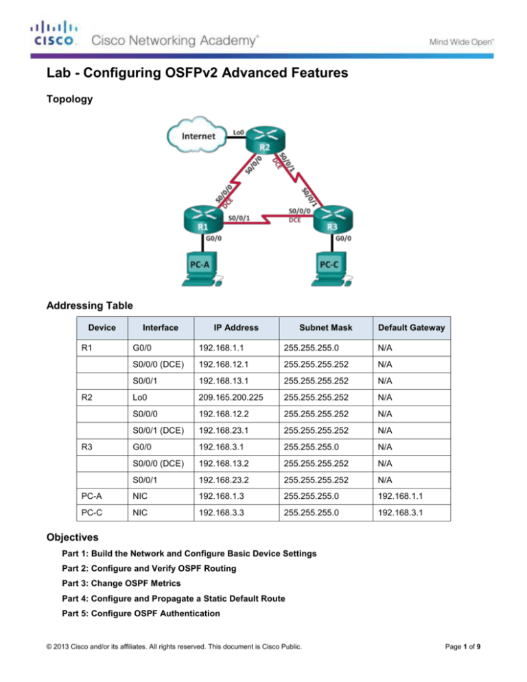
Topology
Addressing Table
Device
R1
Interface
IP Address
Subnet Mask
Default Gateway
G0/0
192.168.1.1
255.255.255.0
N/A
S0/0/0 (DCE)
192.168.12.1
255.255.255.252
N/A
S0/0/1
192.168.13.1
255.255.255.252
N/A
Lo0
209.165.200.225
255.255.255.252
N/A
S0/0/0
192.168.12.2
255.255.255.252
N/A
S0/0/1 (DCE)
192.168.23.1
255.255.255.252
N/A
G0/0
192.168.3.1
255.255.255.0
N/A
S0/0/0 (DCE)
192.168.13.2
255.255.255.252
N/A
S0/0/1
192.168.23.2
255.255.255.252
N/A
PC-A
NIC
192.168.1.3
255.255.255.0
192.168.1.1
PC-C
NIC
192.168.3.3
255.255.255.0
192.168.3.1
R2
R3
Objectives
Part 1: Build the Network and Configure Basic Device Settings
Part 2: Configure and Verify OSPF Routing
Part 3: Change OSPF Metrics
Part 4: Configure and Propagate a Static Default Route
Part 5: Configure OSPF Authentication
© 2013 Cisco and/or its affiliates. All rights reserved. This document is Cisco Public.
Page 1 of 9
Lab - Configuring OSFPv2 Advanced Features
Background / Scenario
Open Shortest Path First (OSPF) has advanced features to allow changes to be made to control metrics,
default route propagation, and security.
In this lab, you will adjust OSPF metrics on the router interfaces, configure OSPF route propagation, and use
Message Digest 5 (MD5) authentication to secure OSPF routing information.
Note: The routers used with CCNA hands-on labs are Cisco 1941 Integrated Services Routers (ISRs) with
Cisco IOS Release 15.2(4)M3 (universalk9 image). Other routers and Cisco IOS versions can be used.
Depending on the model and Cisco IOS version, the commands available and output produced might vary
from what is shown in the labs. Refer to the Router Interface Summary Table at the end of this lab for the
correct interface identifiers.
Note: Make sure that the routers have been erased and have no startup configurations. If you are unsure,
contact your instructor.
Required Resources
3 Routers (Cisco 1941 with Cisco IOS Release 15.2(4)M3 universal image or comparable)
2 PCs (Windows 7, Vista, or XP with terminal emulation program, such as Tera Term)
Console cables to configure the Cisco IOS devices via the console ports
Ethernet and serial cables as shown in the topology
Part 1: Build the Network and Configure Basic Device Settings
In Part 1, you will set up the network topology and configure basic settings on the PC hosts and routers.
Step 1: Cable the network as shown in the topology.
Step 2: Initialize and reload the routers as necessary.
Step 3: Configure basic settings for each router.
a. Disable DNS lookup.
b. Configure device name as shown in the topology.
c.
Assign class as the privileged EXEC password.
d. Assign cisco as the console and vty passwords.
e. Encrypt the clear text passwords.
f.
Configure a MOTD banner to warn users that unauthorized access is prohibited.
g. Configure logging synchronous for the console line.
h. Configure the IP addresses listed in the Addressing Table for all interfaces.
i.
Set the clock rate for all DCE serial interfaces at 128000.
j.
Copy the running configuration to the startup configuration.
Step 4: Configure PC hosts.
Refer to the Addressing Table for PC host address information.
© 2013 Cisco and/or its affiliates. All rights reserved. This document is Cisco Public.
Page 2 of 9
Lab - Configuring OSFPv2 Advanced Features
Step 5: Test connectivity.
At this point, the PCs are unable to ping each other. However, the routers should be able to ping the directly
connected neighbor interfaces, and the PCs should be able to ping their default gateway. Verify and
troubleshoot if necessary.
Part 2: Configure and Verify OSPF Routing
In Part 2, you will configure OSPFv2 routing on all routers in the network and then verify that routing tables
are updated correctly.
Step 1: Configure the router ID on all routers.
Assign 1 as the process ID for this OSPF process. Each router should be given the following router ID
assignments:
R1 Router ID: 1.1.1.1
R2 Router ID: 2.2.2.2
R3 Router ID: 3.3.3.3
Step 2: Configure OSPF network information on the routers.
Step 3: Verify OSPF routing.
a. Issue the show ip ospf neighbor command to verify that each router is listing the other routers in the
network.
b. Issue the show ip route ospf command to verify that all OSPF networks are present in the routing table
on all routers.
Step 4: Test end-to-end connectivity.
Ping PC-C from PC-A to verify end-to-end connectivity. The pings should be successful. If they are not,
troubleshoot as necessary.
Note: It may be necessary to disable the PC firewall for the pings to be successful.
Part 3: Change OSPF Metrics
In Part 3, you will change OSPF metrics using the bandwidth command, the auto-cost referencebandwidth command, and the ip ospf cost command. Making these changes will provide more accurate
metrics to OSPF.
Note: All DCE interfaces should have been configured with a clocking rate of 128000 in Part 1.
Step 1: Change the bandwidth on all serial interfaces to 128Kb/s.
a. Issue the show ip ospf interface brief command to view the default cost settings on the router
interfaces.
R1# show ip ospf interface brief
Interface
Se0/0/1
Se0/0/0
Gi0/0
PID
1
1
1
Area
0
0
0
IP Address/Mask
192.168.13.1/30
192.168.12.1/30
192.168.1.1/24
Cost
64
64
1
State
P2P
P2P
DR
Nbrs F/C
1/1
1/1
0/0
b. Use the bandwidth 128 interface command on all serial interfaces.
© 2013 Cisco and/or its affiliates. All rights reserved. This document is Cisco Public.
Page 3 of 9
Lab - Configuring OSFPv2 Advanced Features
c.
Issue the show ip ospf interface brief command to view the new cost settings.
R1# show ip ospf interface brief
Interface
Se0/0/1
Se0/0/0
Gi0/0
PID
1
1
1
Area
0
0
0
IP Address/Mask
192.168.13.1/30
192.168.12.1/30
192.168.1.1/24
Cost
781
781
1
State
P2P
P2P
DR
Nbrs F/C
1/1
1/1
0/0
Step 2: Change the reference bandwidth on the routers.
a. Issue the auto-cost reference-bandwidth 1000 command on the routers to change the default reference
bandwidth setting to account for Gigabit Ethernet Interfaces.
b. Re-issue the show ip ospf interface brief command to view how this command has changed cost
values.
R1# show ip ospf interface brief
Interface
Se0/0/1
Se0/0/0
Gi0/0
PID
1
1
1
Area
0
0
0
IP Address/Mask
192.168.13.1/30
192.168.12.1/30
192.168.1.1/24
Cost
7812
7812
1
State
P2P
P2P
DR
Nbrs F/C
0/0
0/0
0/0
Note: If the router had Fast Ethernet interfaces instead of Gigabit Ethernet interfaces, then the cost would
now be 10 on those interfaces.
Step 3: Change the route cost.
a. Issue the show ip route ospf command to display the current OSPF routes on R1. Notice that there are
currently two routes in the table that use the S0/0/1 interface.
R1# show ip route ospf
Codes: L - local, C - connected, S - static, R - RIP, M - mobile, B - BGP
D - EIGRP, EX - EIGRP external, O - OSPF, IA - OSPF inter area
N1 - OSPF NSSA external type 1, N2 - OSPF NSSA external type 2
E1 - OSPF external type 1, E2 - OSPF external type 2
i - IS-IS, su - IS-IS summary, L1 - IS-IS level-1, L2 - IS-IS level-2
ia - IS-IS inter area, * - candidate default, U - per-user static route
o - ODR, P - periodic downloaded static route, H - NHRP, l - LISP
+ - replicated route, % - next hop override
Gateway of last resort is not set
O
O
192.168.3.0/24 [110/7822] via 192.168.13.2, 00:00:12, Serial0/0/1
192.168.23.0/30 is subnetted, 1 subnets
192.168.23.0 [110/15624] via 192.168.13.2, 00:00:12, Serial0/0/1
[110/15624] via 192.168.12.2, 00:20:03, Serial0/0/0
b. Apply the ip ospf cost 16000 command to the S0/0/1 interface on R1. A cost of 16,000 is higher than the
accumulated cost of the route through R2 which is 15,624.
© 2013 Cisco and/or its affiliates. All rights reserved. This document is Cisco Public.
Page 4 of 9
Lab - Configuring OSFPv2 Advanced Features
c.
Issue the show ip ospf interface brief command on R1 to view the cost change to S0/0/1.
R1# show ip ospf interface brief
Interface
Se0/0/1
Se0/0/0
Gi0/0
PID
1
1
1
Area
0
0
0
IP Address/Mask
192.168.13.1/30
192.168.12.1/30
192.168.1.1/24
Cost
16000
7812
1
State
P2P
P2P
DR
Nbrs F/C
1/1
1/1
0/0
d. Re-issue the show ip route ospf command on R1 to display the effect this change has made on the
routing table. All OSPF routes for R1 are now being routed through R2.
R1# show ip route ospf
Codes: L - local, C - connected, S - static, R - RIP, M - mobile, B - BGP
D - EIGRP, EX - EIGRP external, O - OSPF, IA - OSPF inter area
N1 - OSPF NSSA external type 1, N2 - OSPF NSSA external type 2
E1 - OSPF external type 1, E2 - OSPF external type 2
i - IS-IS, su - IS-IS summary, L1 - IS-IS level-1, L2 - IS-IS level-2
ia - IS-IS inter area, * - candidate default, U - per-user static route
o - ODR, P - periodic downloaded static route, H - NHRP, l - LISP
+ - replicated route, % - next hop override
Gateway of last resort is not set
O
O
192.168.3.0/24 [110/15625] via 192.168.12.2, 00:05:31, Serial0/0/0
192.168.23.0/30 is subnetted, 1 subnets
192.168.23.0 [110/15624] via 192.168.12.2, 01:14:02, Serial0/0/0
Explain why the route to the 192.168.3.0/24 network on R1 is now going through R2?
_______________________________________________________________________________________
_______________________________________________________________________________________
_______________________________________________________________________________________
Part 4: Configure and Propagate a Static Default Route
In Part 4, you will use a loopback interface on R2 to simulate an ISP connection to the Internet. You will
create a static default route on R2, and then OSPF will propagate that route to the other two routers on the
network.
Step 1: Configure a static default route on R2 to loopback 0.
Configure a default route using the loopback interface configured in Part 1, to simulate a connection to an
ISP.
Step 2: Have OSPF propagate the default static route.
Issue the default-information originate command to include the static default route in the OSPF updates
that are sent from R2.
R2(config)# router ospf 1
R2(config-router)# default-information originate
© 2013 Cisco and/or its affiliates. All rights reserved. This document is Cisco Public.
Page 5 of 9
Lab - Configuring OSFPv2 Advanced Features
Step 3: Verify OSPF static route propagation.
a. Issue the show ip route static command on R2.
R2# show ip route static
Codes: L - local, C - connected, S - static, R - RIP, M - mobile, B - BGP
D - EIGRP, EX - EIGRP external, O - OSPF, IA - OSPF inter area
N1 - OSPF NSSA external type 1, N2 - OSPF NSSA external type 2
E1 - OSPF external type 1, E2 - OSPF external type 2
i - IS-IS, su - IS-IS summary, L1 - IS-IS level-1, L2 - IS-IS level-2
ia - IS-IS inter area, * - candidate default, U - per-user static route
o - ODR, P - periodic downloaded static route, H - NHRP, l - LISP
+ - replicated route, % - next hop override
Gateway of last resort is 0.0.0.0 to network 0.0.0.0
S*
0.0.0.0/0 is directly connected, Loopback0
b. Issue the show ip route command on R1 to verify the propagation of the static route from R2.
R1# show ip route
Codes: L - local, C - connected, S - static, R - RIP, M - mobile, B - BGP
D - EIGRP, EX - EIGRP external, O - OSPF, IA - OSPF inter area
N1 - OSPF NSSA external type 1, N2 - OSPF NSSA external type 2
E1 - OSPF external type 1, E2 - OSPF external type 2
i - IS-IS, su - IS-IS summary, L1 - IS-IS level-1, L2 - IS-IS level-2
ia - IS-IS inter area, * - candidate default, U - per-user static route
o - ODR, P - periodic downloaded static route, H - NHRP, l - LISP
+ - replicated route, % - next hop override
Gateway of last resort is 192.168.12.2 to network 0.0.0.0
O*E2
C
L
O
C
L
C
L
O
c.
0.0.0.0/0 [110/1] via 192.168.12.2, 00:02:57, Serial0/0/0
192.168.1.0/24 is variably subnetted, 2 subnets, 2 masks
192.168.1.0/24 is directly connected, GigabitEthernet0/0
192.168.1.1/32 is directly connected, GigabitEthernet0/0
192.168.3.0/24 [110/15634] via 192.168.12.2, 00:03:35, Serial0/0/0
192.168.12.0/24 is variably subnetted, 2 subnets, 2 masks
192.168.12.0/30 is directly connected, Serial0/0/0
192.168.12.1/32 is directly connected, Serial0/0/0
192.168.13.0/24 is variably subnetted, 2 subnets, 2 masks
192.168.13.0/30 is directly connected, Serial0/0/1
192.168.13.1/32 is directly connected, Serial0/0/1
192.168.23.0/30 is subnetted, 1 subnets
192.168.23.0 [110/15624] via 192.168.12.2, 00:05:18, Serial0/0/0
Verify end-to-end connectivity by issuing a ping from PC-A to the ISP interface address 209.165.200.225.
Were the pings successful? ______________
© 2013 Cisco and/or its affiliates. All rights reserved. This document is Cisco Public.
Page 6 of 9
Lab - Configuring OSFPv2 Advanced Features
Part 5: Configure OSPF Authentication
OSPF authentication can be set up at the link level or the area level. There are three authentication types
available for OSPF authentication: Null, plain text, or MD5. In Part 5, you will set up OSPF MD5
authentication, which is the strongest available.
Step 1: Set up MD5 OSPF authentication on a single link.
a. Issue the debug ip ospf adj command on R2 to view OSPF adjacency messages.
R2# debug ip ospf adj
OSPF adjacency debugging is on
b. Assign an MD5 key for OSPF Authentication on R1, interface S0/0/0.
R1(config)# interface s0/0/0
R1(config-if)# ip ospf message-digest-key 1 md5 MD5KEY
c.
Activate MD5 authentication on R1, interface S0/0/0.
R1(config-if)# ip ospf authentication message-digest
OSPF debug messages informing you of a Mismatched Authentication type displays on R2.
*Mar 19 00:03:18.187: OSPF-1 ADJ
Se0/0/0: Rcv pkt from 192.168.12.1 : Mismatched
Authentication type. Input packet specified type 2, we use type 0
d. Issue the u all command, which is the shortest version of the undebug all command on R2 to disable
debugging.
e. Configure OSPF authentication on R2, interface S0/0/0. Use the same MD5 password you entered for
R1.
f.
Issue a show ip ospf interface s0/0/0 command on R2. This command displays the type of
authentication at the bottom of the output.
R2# show ip ospf interface s0/0/0
Serial0/0/0 is up, line protocol is up
Internet Address 192.168.12.2/30, Area 0, Attached via Network Statement
Process ID 1, Router ID 2.2.2.2, Network Type POINT_TO_POINT, Cost: 7812
Topology-MTID
Cost
Disabled
Shutdown
Topology Name
0
7812
no
no
Base
Transmit Delay is 1 sec, State POINT_TO_POINT
Timer intervals configured, Hello 10, Dead 40, Wait 40, Retransmit 5
oob-resync timeout 40
Hello due in 00:00:03
Supports Link-local Signaling (LLS)
Cisco NSF helper support enabled
IETF NSF helper support enabled
Index 1/1, flood queue length 0
Next 0x0(0)/0x0(0)
Last flood scan length is 1, maximum is 1
Last flood scan time is 0 msec, maximum is 0 msec
Neighbor Count is 1, Adjacent neighbor count is 1
Adjacent with neighbor 1.1.1.1
Suppress hello for 0 neighbor(s)
Message digest authentication enabled
Youngest key id is 1
© 2013 Cisco and/or its affiliates. All rights reserved. This document is Cisco Public.
Page 7 of 9
Lab - Configuring OSFPv2 Advanced Features
Step 2: Set up OSPF authentication at the area level.
a. Issue the area 0 authentication command to set MD5 authentication for OSPF Area 0 on R1.
R1(config)# router ospf 1
R1(config-router)# area 0 authentication message-digest
b. This option still requires that you assign the MD5 password at the interface level.
R1(config)# interface s0/0/1
R1(config-if)# ip ospf message-digest-key 1 md5 MD5KEY
c.
Issue the show ip ospf neighbor command on R3. R1 no longer has an adjacency with R3.
R3# show ip ospf neighbor
Neighbor ID
2.2.2.2
0
Pri
State
FULL/ -
Dead Time
Address
00:00:31
192.168.23.1
Interface
Serial0/0/1
d. Set up area authentication on R3 and assign the same MD5 password to interface S0/0/0.
R3(config)# router ospf 1
R3(config-router)# area 0 authentication message-digest
R3(config-router)# interface s0/0/0
R3(config-if)# ip ospf message-digest-key 1 md5 MD5KEY
e. Issue the show ip ospf neighbor command on R3. Notice that R1 is now showing as a neighbor, but R2
is missing.
R3# show ip ospf neighbor
Neighbor ID
1.1.1.1
0
Pri
State
FULL/ -
Dead Time
Address
00:00:38
192.168.13.1
Interface
Serial0/0/0
Why is R2 no longer showing as an OSPF neighbor?
____________________________________________________________________________________
f.
Configure R2 to perform area-level MD5 authentication.
R2(config)# router ospf 1
R2(config-router)# area 0 authentication message-digest
g. Assign MD5KEY as the MD5 password for the link between R2 and R3.
h. Issue the show ip ospf neighbor command on all routers to verify that all adjacencies have been reestablished.
R1# show ip ospf neighbor
Neighbor ID
3.3.3.3
2.2.2.2
Pri
0
0
State
FULL/
FULL/
-
Dead Time
00:00:39
00:00:35
Address
192.168.13.2
192.168.12.2
Interface
Serial0/0/1
Serial0/0/0
-
Dead Time
00:00:36
00:00:32
Address
192.168.23.2
192.168.12.1
Interface
Serial0/0/1
Serial0/0/0
R2# show ip ospf neighbor
Neighbor ID
3.3.3.3
1.1.1.1
Pri
0
0
State
FULL/
FULL/
© 2013 Cisco and/or its affiliates. All rights reserved. This document is Cisco Public.
Page 8 of 9
Lab - Configuring OSFPv2 Advanced Features
R3# show ip ospf neighbor
Neighbor ID
2.2.2.2
1.1.1.1
Pri
0
0
State
FULL/
FULL/
-
Dead Time
00:00:33
00:00:39
Address
192.168.23.1
192.168.13.1
Interface
Serial0/0/1
Serial0/0/0
Reflection
1. What is the easiest and preferred method of manipulating OSPF route costs?
_______________________________________________________________________________________
_______________________________________________________________________________________
2. What does the default-information originate command do for a network using the OSPF routing protocol?
_______________________________________________________________________________________
_______________________________________________________________________________________
3. Why is it a good idea to use OSPF authentication?
_______________________________________________________________________________________
_______________________________________________________________________________________
_______________________________________________________________________________________
_______________________________________________________________________________________
_______________________________________________________________________________________
Router Interface Summary Table
Router Interface Summary
Router Model
Ethernet Interface #1
Ethernet Interface #2
Serial Interface #1
Serial Interface #2
1800
Fast Ethernet 0/0
(F0/0)
Fast Ethernet 0/1
(F0/1)
Serial 0/0/0 (S0/0/0)
Serial 0/0/1 (S0/0/1)
1900
Gigabit Ethernet 0/0
(G0/0)
Gigabit Ethernet 0/1
(G0/1)
Serial 0/0/0 (S0/0/0)
Serial 0/0/1 (S0/0/1)
2801
Fast Ethernet 0/0
(F0/0)
Fast Ethernet 0/1
(F0/1)
Serial 0/1/0 (S0/1/0)
Serial 0/1/1 (S0/1/1)
2811
Fast Ethernet 0/0
(F0/0)
Fast Ethernet 0/1
(F0/1)
Serial 0/0/0 (S0/0/0)
Serial 0/0/1 (S0/0/1)
2900
Gigabit Ethernet 0/0
(G0/0)
Gigabit Ethernet 0/1
(G0/1)
Serial 0/0/0 (S0/0/0)
Serial 0/0/1 (S0/0/1)
Note: To find out how the router is configured, look at the interfaces to identify the type of router and how many
interfaces the router has. There is no way to effectively list all the combinations of configurations for each router
class. This table includes identifiers for the possible combinations of Ethernet and Serial interfaces in the device.
The table does not include any other type of interface, even though a specific router may contain one. An
example of this might be an ISDN BRI interface. The string in parenthesis is the legal abbreviation that can be
used in Cisco IOS commands to represent the interface.
© 2013 Cisco and/or its affiliates. All rights reserved. This document is Cisco Public.
Page 9 of 9

