Science, Intelligent Design and Evolution
advertisement
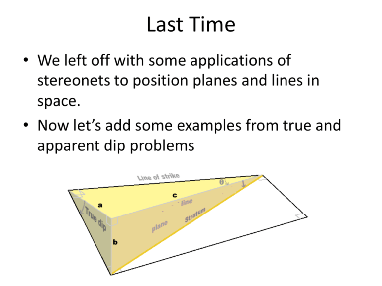
Last Time • We left off with some applications of stereonets to position planes and lines in space. • Now let’s add some examples from true and apparent dip problems 4: Apparent Dip knowing True Dip The attitude of a dike is 205, 65 (S25W, 65SE = N25E, 65SE). What is its apparent dip on a vertical quarry wall trending 350 = N10W? Visualize the problem (a) and plot the dike (b) Apparent Dip knowing true dip The attitude of a dike is 205, 65 (N25E, 65SE). What is its apparent dip on a vertical quarry wall trending 350 = N10W? Return North to 0o, then plot the vertical quarry wall N10W. Apparent Dip knowing true dip The attitude of a dike is 205, 65 (N25E, 65SE). What is its apparent dip on a vertical quarry wall trending 350? d. Rotate the transparency so the wall is along the vertical axis. The apparent dip angle is from the primitive to the intersection, 52o. 5. True Dip from two Apparent Dips Question: A layer intersecting a road cut trends 256, 32. The same layer intersects the road cut around a bend and trends 125, 27. What is the strike & dip of the layer? Visualize the problem (a) and then plot the intersections for the road cuts and the layer (b & c) Mark 256, rotate it to vertical Count in apparent dip 32o Mark 125, rotate it to vertical Count in apparent dip 27o True Dip from two Apparent Dips Question: A layer intersecting a road cut trends 256, 32. The same layer intersects the road cut around a bend and trends 125, 27. What is the strike & dip of the layer? Because the two road cut intersections lie on the dike, rotate the transparency so the two points line on the same great circle. Draw the great circle (d). Notice they define the plane of the dike. True Dip from two Apparent Dips Question: A layer intersecting a road cut trends 256, 32. The same layer intersects the road cut around a bend and trends 125, 27. What is the strike & dip of the layer? That great circle is the attitude of the dike; measure its dip along the equator from the primitive to the great circle (d). Now rotate the transparency so that its N coincides with 0 on the net. Measure the strike and note its dip direction (e), here about N77W 54S Structural Geology Stereographic Projections Part 2 - Folds So far, we have represented a plane on the stereographic projection as a great circle. If we plot many planes, the projection soon gets cluttered. A plane, however, can be represented by its pole, the unique line drawn perpendicular to the plane. Because the pole is a line, it plots as a point on the stereographic projection. Poles to Planes Poles to Planes 1. A bed is 330, 50 (N30W, 50SW) Plot the plane and its pole. Plot the plane as usual (6-2b). Then plot the point 90o away from the plane along the horizontal axis and that is the pole. Mark 330, rotate it to vertical Return north to 0o Count in dip 50o , draw in great circle, plot pole 90o opposite Cylindrical Folds • Many folds are cylindrical; that is, the rocks have been deformed by simple bending without twisting. The axis, or hinge, of the fold is the line of sharpest curvature of any given layer. Wherever we measure the strike and dip of beds on such a fold, we find that the attitudes are always parallel to a common direction, and that direction is also parallel to the axis of the fold. • In the most general sense, a cylinder is defined mathematically as a surface that is generated by a straight line that always moves parallel to itself. The cylinder need not be circular. While folds are usually not perfectly cylindrical, many are sufficiently close to make this a useful approximation. This and the next slide are courtesy of Steve Dutch Cylindrical Folds • Some consequences of cylindrical geometry are: • The line that generates the cylinder is parallel to the fold axis. • All planes tangent to the cylinder are tangent along a line parallel to the fold axis. • All planes tangent to the cylinder are parallel to the fold axis. • Therefore, any two planes tangent to the cylinder intersect in a line parallel to the fold axis. • All parallel cross-sections of the cylinder are identical. • Strike and dip measurements on a cylindrical fold define planes parallel to the fold axis. Any two of these planes intersect in a line parallel to the fold axis. This and the previous slide are courtesy of Steve Dutch Poles to Planes 2. Intersection line. The layers on the limbs of a fold will intersect along a line parallel to the fold axis. We can get the azimuth and plunge of a fold from this. Limb A is 200, 60 and limb B is 060, 40 b. Plot layer A and its pole. c. Plot layer B and its pole. Poles to Planes Intersection line. The layers on the limbs of a fold will intersect along a line parallel to the fold axis. d. Now rotate the net so that the 2 poles of the layers line up along a great circle and dash in that great circle. Measure the angle, here 22o. As a general rule, poles to beds folded cylindrically will all plot on a great circle perpendicular to the fold axis. e. Return North to 0 Draw a line perpendicular to the great circle P2 P1 through the intersection F. This is the fold axis. Read its orientation, here N35E. Include in your label the angle from the intersection to the primitive. This is the plunge of the fold axis. Here it is 22o.
