Supercar-Schematics
advertisement
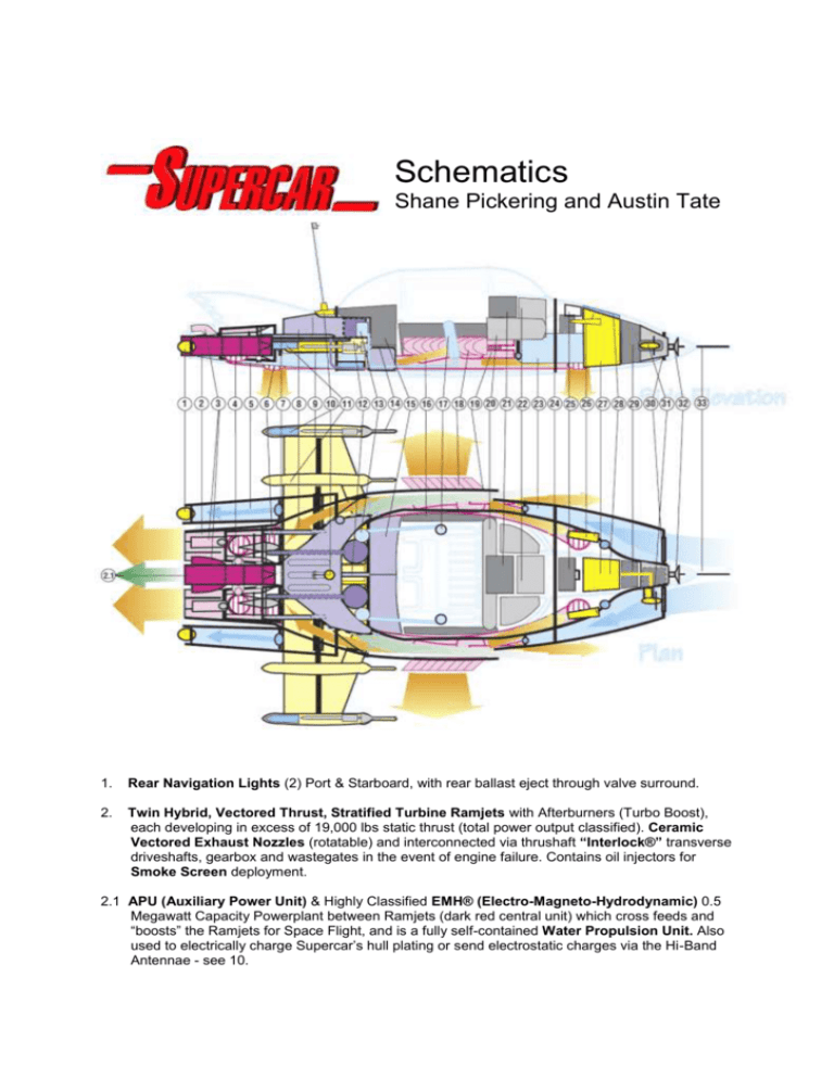
Schematics Shane Pickering and Austin Tate 1. Rear Navigation Lights (2) Port & Starboard, with rear ballast eject through valve surround. 2. Twin Hybrid, Vectored Thrust, Stratified Turbine Ramjets with Afterburners (Turbo Boost), each developing in excess of 19,000 lbs static thrust (total power output classified). Ceramic Vectored Exhaust Nozzles (rotatable) and interconnected via thrushaft “Interlock®” transverse driveshafts, gearbox and wastegates in the event of engine failure. Contains oil injectors for Smoke Screen deployment. 2.1 APU (Auxiliary Power Unit) & Highly Classified EMH® (Electro-Magneto-Hydrodynamic) 0.5 Megawatt Capacity Powerplant between Ramjets (dark red central unit) which cross feeds and “boosts” the Ramjets for Space Flight, and is a fully self-contained Water Propulsion Unit. Also used to electrically charge Supercar’s hull plating or send electrostatic charges via the Hi-Band Antennae - see 10. 3. Vectored Flight Attitude Nozzles controlling pitch and yaw movement (4). 4. Ramjet Vectored Thrust Outlet Nozzle from Ramjet Engines ducted through to Retro Jets and Adjustable VTOL Nozzles (4). 5. Rear Ballast Tanks with Ram Intake Valves (2), Port & Starboard. 6. Rear Vectored VTOL Jet Nozzles (2) interconnected to Fwd. VTOL Jet Nozzles (2), featuring CAD (Cushion Augmentation Devices) for added Roll, Pitch control and Ground Effect Mode. Independently computer controlled depending on selected Flight Mode and fed from main Ramjets & EMH® Powerplant. 7. Main Fuel Feed Injector Lines (6), Port & Starboard, to Ramjets with Emergency Cutoff Valves. 8. Main Fuel Tank containing Classified AvGas® and tapered to airflow ducting. Separate Liquid Oxygen & Hydrogen Tanks (Circular units) with built in refrigeration units for Spaceflight & Marine operation. Auxiliary Fuel Tank under Luggage Compartment - see also 15 9. Retractable Wing Box Surround & hydraulics. 10. Combined Hi-Band UHF/VHF Antennae and ClearVu® Periscope Receptor (detachable at top of aerial), with Electrostatic discharge coil from EMH® unit. 11. Rear Ballistic Parachute Recovery Pack (2), Port & Starboard, housed in wing nacelle cones (fired in unison with front mounted unit – see also 28. 12. Wing Extenuator Engine Pump & Backup. 13. Oxygen Regenerators, Pressurisation & Airconditioning Pumps (2), Port & Starboard, fed to main pressurised cabin through Rear Bulkhead “Firewall”. 14. Wing Nacelle Multi-mode Avionic & Marine Sensor Probes (2), Port & Starboard, connected to ClearVu® Read outs. Includes INS (Inertial Navigation System) aerials for position fixing and ground terrain sensors for moving map display read-out. 15. Split Luggage/Equipment Storage Bay behind rear folding seats. (Auxiliary Fuel Tank under Luggage Compartment - see 8. 16. Electrically operated Flexiglass® Canopy Storage & lifters. (Top Canopy splits into two halves and slides down tracks “inside” side windows). Entire Canopy removable for maintenance. 17. Oxygen Bottles and Pressurisation outlet & recirculation systems embedded into Front Seats, fed directly from Oxygen, Pressurisation and Airconditioning Units in rear - see also 13. 18. Retro Jet Heat Extractor Vanes (2) Port & Starboard, containing vectored thrust vents for sideways movement. 19. Twin Retro Jets (2), Port & Starboard, fed from main VTOL ducts with EMH® (Electro-MagnetoHydrodynamic) accelerators giving enormous braking power. 20. Main Flight Avionics Bay and Marine instruments including triplicated Flight Computer Backups with built in Communication Array. Microphone is simply voice activated from pilot. 21. Multi-mode ClearVu® CRT instrumentation, flight data, and systems status read-out. 22. Main Computer Core Processor Unit. 23. Fwd. Ballast Tanks (2), Port & Starboard with Ram intake valves (front), and bleed pumps into main duct inlets. Closed at front when Ballast Tanks are operational allowing them to be “flooded”, drained and trimmed. 24. Fwd. Pressure Bulkhead “Firewall”. 25. Fwd. Mounted Multi-Purpose Optional Equipment Bay, (which can contain Removable Rocket Gun Mount and armament unit (under), additional Oxygen Supply for Space Flight, etc.). 26. Navigation/Landing/Search lights (2), Port & Starboard, with ILS (Instrument Landing System) sensor antennas. 27. Main 24-volt Batteries (2) with backup, insulated electronics and power coil. Used to initially start APU (which charges each engine). 28. Fwd. Ballistic Parachute Recovery Pack (hidden under flush panel). 29. Main Sensor Probe Circuitry and “Remote®” Receiver. 30. Fwd. Ram Intake Valvegate (for air or water feed) can be regulated (opened or closed) for ballast operation. Also cools Avionics Bay. 31. Emergency Generator, wind/water driven with folding turbine blades (retractable - shown in extended position, normally housed in centre unit). Used only if other electrical systems completely fail and if Supercar has forward motion in atmosphere or water. 32. Main Radar/Sonar/Sensor Array and “Remote®” pick-up connected to ClearVu® Read-out. 33. Fwd. Flight Instrument and ClearVu® Pitot Boom Antennae. Supercar internal schematic technical concept, text and drawings by Shane Pickering 1999 with technical assistance from Austin Tate. Original Supercar designed by Reg Hill. Supercar exterior based on Phil Rae Blueprints and 3-D renderings and model by Mick Imrie and Austin Tate. This is fan produced material to promote the shows of Gerry Anderson and provided for your enjoyment, and must not be used for any commercial purpose.

