PHY2054_02-10
advertisement
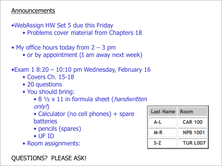
Announcements •WebAssign HW Set 5 due this Friday • Problems cover material from Chapters 18 • My office hours today from 2 – 3 pm • or by appointment (I am away next week) •Exam 1 8:20 – 10:10 pm Wednesday, February 16 • Covers Ch. 15-18 • 20 questions • You should bring: • 8 ½ x 11 in formula sheet (handwritten only!) • Calculator (no cell phones) + spare batteries • pencils (spares) • UF ID • Room assignments: QUESTIONS? PLEASE ASK! From last time emf Internal resistance Terminal voltage ΔV = ε – Ir Resistors in Series Same current Req = R1 + R2 + R3 + … Resistors in parallel Same voltage drop 1 1 1 1 = + + +… Req R1 R2 R3 Kirchhoff’s Rules 1. Junction Rule Sum of the currents entering a junction = the sum of the currents leaving the junction Σ Iin = Σ Iin Conservation of charge 2. Loop Rule Sum of the ΔV across all the elements around any closed circuit loop must be zero Σ Vloop = 0 A statement of Conservation of Energy I 1 = I2 + I3 More About the Loop Rule Traveling around the loop from a to b In (a), the resistor is traversed in the direction of the current, the potential across the resistor is –IR In (b), the resistor is traversed in the direction opposite of the current, the potential across the resistor is +IR Even More About the Loop Rule In (c), the source of emf is traversed in the direction of the emf (from – to +), the change in the electric potential is +ε In (d), the source of emf is traversed in the direction opposite of the emf (from + to -), the change in the electric potential is -ε Problem-Solving Strategy – Kirchhoff’s Rules Draw the circuit diagram and assign labels and symbols to all known and unknown quantities Assign directions to the currents. Apply the junction rule to any junction in the circuit Apply the loop rule to as many loops as are needed to solve for the unknowns Solve the equations simultaneously for the unknown quantities Check your answers Example Problem 18.26 A dead battery is charged by connecting it to a live battery of another car with jumper cables. Determine the amount of current in the starter and in the dead battery. RC Circuits DC circuits containing capacitors and resistors, having time-varying currents/charges When S is closed, the capacitor starts to charge The capacitor charges until it reaches its maximum charge (Qmax = Cε) Once the capacitor is fully charged, I 0 Charging Capacitor in an RC Circuit The charge on the capacitor varies with time q(t) = Qmax(1 – e-t/RC) Can define a time constant: = RC is the time required for the q to increase from zero to 63.2% (= 1 – e) of its maximum Notes on Time Constant In a circuit with a large time constant, the capacitor charges very slowly The capacitor charges very quickly if there is a small time constant After t = 10 , the capacitor is over 99.99% charged Discharging Capacitor in an RC Circuit When a charged capacitor is placed in the circuit, it can be discharged q = Qe-t/RC The charge decreases exponentially At t = = RC, the charge decreases to 0.368 Qmax In other words, in one time constant, the capacitor loses 63.2% of its initial charge Example Problem 18.33 Consider a series RC circuit for which R = 1.0 MΩ, C = 5 μF, and ε = 30 V. Find the charge on the capacitor 10 s after the switch is closed. Solution to 18.26 Solution to 18.33

![Sample_hold[1]](http://s2.studylib.net/store/data/005360237_1-66a09447be9ffd6ace4f3f67c2fef5c7-300x300.png)


