Document
advertisement
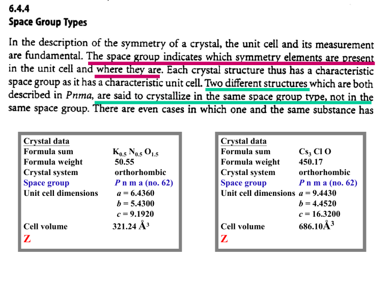
Crystal data
Formula sum
Formula weight
Crystal system
Space group
Unit cell dimensions
Cell volume
Z
K0.5 N0.5 O1.5
50.55
orthorhombic
P n m a (no. 62)
a = 6.4360
b = 5.4300
c = 9.1920
321.24 Å3
Crystal data
Formula sum
Formula weight
Crystal system
Space group
Unit cell dimensions
Cell volume
Z
Cs3 Cl O
450.17
orthorhombic
P n m a (no. 62)
a = 9.4430
b = 4.4520
c = 16.3200
686.10Å3
Atomic coordinates
Atom
K1
N1
O1
O2
Wyck.
4c
4c
4c
8d
Occ.
0.5
0.5
0.5
x
0.25510
0.41560
0.40980
0.41290
y
1/4
1/4
1/4
0.45010
TITL *Niter-K(NO3)-[Pnma]-Holden J R, Dickinson C W
CELL 1.54180 6.436 5.430 9.192 90.0 90.0 90.0
SYMM P n m a (62)
UNIT 8 60 24 4
SFAC K N O
K1 1 0.25510 0.25000 0.41640 10.5000 =
0.03110 0.23800 0.02480 0.00000 0.00110 0.00000
N1 2 0.41560 0.25000 0.75510 10.5000 =
0.01920 0.02500 0.02970 0.00000 0.00160 0.00000
O1 3 0.40980 0.25000 0.89070 10.5000 =
0.05000 0.04070 0.02720 0.00000 -0.0080 0.00000
O2 3 0.41290 0.45010 0.68640 11.0000 =
0.04930 0.02680 0.03920 -0.0038 0.00520 0.00640
END
z
0.41640
0.75510
0.89070
0.68640
p. 58
Cell unchanged but with
lower crystal class
Cell changed with the
same symmetry
Cell changed with a
different Bravais Lattice
Space groups (and enantiomorphous pairs) that are uniquely determinable from
the symmetry of the diffraction pattern and from systematic absences are
shown in bold-type.
Point groups w/o inversion centers or
mirror planes are emphasized by boxes.
Space groups (and enantiomorphous pairs) that are uniquely determinable from
the symmetry of the diffraction pattern and from systematic absences are
shown in bold-type.
Point groups w/o inversion centers or mirror planes are emphasized by boxes.
*
*
*
*
a*
*
*
*
*
a*
=60o
*
*
A complete data set covers all 8 octants of r.l. points.
--- --- --(hk) (hk)
- - - (hk) (hk)
----- ---
(hk) (hk) (hk) (hk)
p.61
(hk)
[hk]
Equivalent planes
{hk}
<hk>
Hexagonal Axes vs. Rhombohedral Axes
Two ways to relate rhombohedral indices to hexagonal indices,
the obverse and reverse relationship.
The hexagonal cell :
Rhombohedral cell:
a1, a2, c
r1 , r2 , r3
Obverse hexagonal axes:
a1 = r2 – r3
a2 = r3 – r1
c = r1 + r 2 + r3
Reverse hexagonal axes:
a1 = r3 – r2
a2 = r1 – r3
c = r1 + r 2 + r3
Hexagonal Axes vs. Rhombohedral Axes
The hexagonal cell :
Rhombohedral cell:
a1, a2, c and indices (h k .)
r1, r2 , r3 and indices (m n p)
Obverse hexagonal axes:
a1 = r2 – r3
a2 = r3 – r1
c = r1 + r2 + r3
h=
n–p
k = -m + p
=m+n+p
-h + k + = 3p
Reverse hexagonal axes:
a1 = r3 – r2
a2 = r1 – r3
c = r1 + r2 + r3
h - k + = 3p
Obverse H vs. R:
Choice of wavelength
Parameters in intensity data collection
Resolution: 2/ |hmax| = dhk-1
Resolution: 2/ |hmax| = dhk-1
dhk ½
dhk ½
Data Processing
1. Data Reduction
Preliminary manipulation of intensities—their conversion to a correct, more usable form
Decay correction
Cause 1: due to unstable crystal – decomposing or slipping
Cause 2: due to unstable X-ray source
– instrument misalignment or instability in tube voltage
Point-detector case: Corrections can be made based on a certain standard reflections
Typical behavior of the relative intensities of threereflections of a crystal monitored
with a diffractometer at different times after exposure begins
Lp correction
“L” stands for Lorenz factor:
Cause : the r.l. point have a non-negligible volume so that it will have different
angular speed when passing through the Ewald sphere (i.e. a higher intensity
when in diffracting position for a longer time).
linear velociy at
point p
angular
velocity
L time = / (|r*|cos)
|r*| = 2sin /
L
= 1/sin2
(the simplest possible form)
Different forms of the L factor may be given for different experimental arrangements.
“p“ stands for polarization factor
The diffracted X-ray beam is polarized relative to the incident beam.
unpolarized
rays
E+ E//cos2θ
s1
E+ E//
Io E2+ E// 2
s0
I E2+ (E// cos2θ) 2
p = I/Io
Diffraction circle
Case 1: no monochromator :
p = (1+ cos22θ)/2
Case 2: with monochromator : The beam is further polarized when
monochrator(s) is (are) used.
(a) when s0, s1, and s2 are co-planar,
p = (1+ cos22θcos22θM)/ (1+ cos22θM)
(b) when s0, s1, and s2 are not co-planar,
p = (cos22θ + cos22θM)/ (1+ cos22θM)
Lp factor: (1+ cos22θ)/2sin2
and
Irel = Iobs/Lp ; Irel = I/Lp
Absorption correction
I = Ioe-t
The path lengths of the beams reflected from the two small elements
of the crystal, A and B, are different for different reflections
(1) Relative transmission factor plotted as a
function of angle for a reflection chosen with a
value close to 90o. The rotation curve can
be used to make an absorption correction.
(2) Empirical absorption correction may also be
applied based on the intensity variations in
symmetry-equivalent reflections.
rotation
Transmission factor
The absorption effect depends
on the crystal’s shape, size,
and density. This effect is
much more severe at
low 2θ angles.
ABSORPTION Correction
(i) applied before refinement (in the data reduction stage)
(ii) applied during refinement by an input of the precise
description of the crystal shape
2. Data Averaging
The intensity data are averaged over all symmetry-equivalent reflections.
Friedel’s Law
indicating that
Ihk Ihk ( Ihk Ihk )
Eleven Laue Symmetry Groups
–
– –
–
–
1 2/m mmm 4/m 4/mmm 3 3m 6/m 6/mmm m3 m3m
Iiave = N Ii /N ( i = 1 to n, n = no. symmetry equivalents
)
The value of I is used to decide which
datamis a real signal or just a noise.
Rint = (Ii - Iiave)/ Ii
HW: List the intensities and their esd’s for all
symmetry equivalents of the reflections
(3 2 6), (0 2 6), (9 0 6) and (3 3 0) in Xtal01.
Calculate their average I and sigma I. What is
the Rint just for this group of reflections?
Pattern Decompostion
Extract Bragg-peak intensity from powder pattern
Electron-density function
(x,y,z)
FT
FT
{Fhkl}
Chapter 8 Structure Solution
(1) The phase problem
To solve a crystal structure is to solve the phase problem.
Why? Simply because the “phase” of the diffracted wave is missing in
diffraction intensity measurements, i. e., only the amplitudes of the diffracted
waves are measured in experiments:
Ihkl FhklF*hkl → Fhkl
phase angle
hkl = tan-1(B/A)
Complex form Fhkl= Ahkl + iBhkl = |Fhkl|exp(ihkl)
(x,y,z)
FT
FT
Fhklexp(ihkl)
How to Solve the Phase Problem?
1. Patterson manipulation methods
cal
{Fhkl}
FT
Ihkl → P(u,v,w) → (xH,yH,zH) →
Bragg intensity
Patterson Function
some located atoms
Heavy-Atom methods; Superposition methods
{cal
hkl}
initially derived phases
Heavy-Atom methods;
To find the position
of a heavy atom, one
must utilize the
“Harker vectors”,
which correspond to
vectors formed
between t symmetryrelated atoms. For
example, in the
space group P21/c,
there are three kinds
of Harker vectors,
namely, (u,v,w),
(u,½,w), and (0,v, ½).
The two chlorine atoms are at
(0.113, 0.912, 0.080) and (0.295, 0.731, 0.383).
The first 23 strongest Patterson peaks are
shown to the right:
Harker lines of (0,v, ½) type are:
peaks #2, #8, #16
Harker planes of (u,½,w) type are:
#3, #10, #11, #15
It is clear to see that from peaks #2 and #3, the
atomic coordinate of the first chlorine atom, Cl1,
could be derived; and from peaks #8 and #10,
the coordinates of the second chlorine atom ,
Cl2, could be obtained.
2. Direct methods
(x,y,z)
FT
FT
obs
cal
Fhklexp(ihkl
)
Crystal Structure Determination and
Refinement Using the
Bruker AXS SMART APEX System
Flowchart for Method
Select, mount, and opti call y ali gn a sui tabl e crystal
Eval uate crystal quali ty; obtain uni t cel l geometry
and prel iminary symmetry informati on
Measure intensity data
Data reducti on
Sol ve the structure
Adapted from William Clegg
“Crystal Structure Determination”
Oxford 1998.
Complete and refi ne the structure
Interpret the resul ts
Select and Mount the Crystal
• Use microscope
• Size: ~0.4 (±0.2) mm
• Transparent, faces, looks single
• Epoxy, caulk, oil, grease to affix
• Glass fiber, nylon loop, capillary
Goniometer Head
Goniometer
Goniometer Assembly
project database
default settings
detector calibration
SMART
ASTRO
setup
sample screening
data collection strategy
data collection
SAINTPLUS
new project
change parameters
SAINT: integrate
SADABS: scale & empirical absorption correction
SHELXTL
new project
XPREP: space group determination
XS: structure solution
XL: least squares refinement
XCIF: tables, reports
George M. Sheldrick
Professor, Director of Institute and part-time programming technician
1960-1966: student at Jesus College and Cambridge University, PhD
(1966)
with Prof. E.A.V. Ebsworth entitled "NMR Studies of Inorganic
Hydrides"
1966-1978: University Demonstrator and then Lecturer at Cambridge
University; Fellow of Jesus College, Cambridge
Meldola Medal (1970), Corday-Morgan Medal (1978)
1978-now: Professor of Structural Chemistry at the University of
Goettingen
Royal Society of Chemistry Award for Structural Chemistry (1981)
Leibniz Prize of the Deutsche Forschungsgemeinschaft (1989)
Member of the Akademie der Wissenschaften zu Goettingen (1989)
Patterson Prize of the American Crystallographic Association (1993)
Author of more than 700 scientific papers and of a program called
SHELX
Interested in methods of solving and refining crystal structures (both
small
molecules and proteins) and in structural chemistry
email: gsheldr@shelx.uni-ac.gwdg.de
fax: +49-551-392582
(1) Concept of the least-squares refinements
Mathematical basis of Least Squares method
• A series of unknowns: X1, X2, …., Xm
• A series of observations: f1, f2, …., fn
a11X1 + a12X2 + …+ a1m Xm = f1
• the coefficients a’s are known and
(i) more equations than unknowns, i. e. n > m,
(ii) the observations are not perfect
(iii) these n equations are not fully consistent
Need “Least squares” method !
A: Linear case:
a11X1 + a12X2 + …+ a1m Xm = f1
a21X1 + a22X2 + …+ a2m Xm = f2
…
an1X1 + an2X2 + …+ anm Xm = fn
{aij} are known and n > m
The error:
nxm
m x1
AX= F
n x1
n equations for n
observations and to
solve m unknowns
e1 = a11X1 + a12X2 + …+ a1m Xm– f1
e2 = a21X1 + a22X2 + …+ a2m Xm – f2
…
en = an1X1 + an2X2 + …+ anm Xm – fn
We want to get Xi’s when S = e12 + e22 + … + en2 is minimum
i. e. min (S) = min (i wi ei2 )
weighting factor
S is the sum of squares of what you calculate minus what you observed
Minimizing “S”
(a) substitute equations for S
n
n
m
i 1
j 1
S wi ei [wi aij x j f j ]2
2
i 1
(b) find the minimum
S
0
X j
For all j = 1 , 2 , 3 , · · · · · · , m
(c) then we obtain the normal equation
m
a
j 1
ki
b
ij
n
akj wk x j aki f k wk
k
m
j 1
n
x j ci
k 1
i=1,2,·······,m
the normal equation
xj
(d) Solve the m simultaneous eqn for x, i.e. the estimate
of
or
WA Xˆ WF
AT WA Xˆ AT WF
Xˆ AT WA
1
AT WF
* must calculate matrix B
mm
B
Normal eqns
B-1
x̂
the soln:Xˆ B1 ATWF
Question: How good are X’s?
*must estimate the “precision of the derived unknowns ( parameters )”
Define : variance - covariance matrix
12 12 ............ 1n
2
21 2 ............ 2 n
V
........... 2
n
n1 n 2
(ij= ji)
Correlation coefficient:
ij
ij
2
i
2
j
1
1
2
V A A
T
2
( ii 1)
common variance
Common variance
2
2
w
e
i i
nm
i
Example: x1 = 2
x2 = 4
x3 = 6
2x1+3x2+x3 = 21
x1+2x2+x3 = 17
or
m=3
n=5
2
2
x
Bij1 wi ei2
nm
j
we
x
i
j
xi , xk
2
i
Bij
1
n
m
we
i
Bik
100
010
A 001 ; X
231
121
AT
T
A
2
x1
4
x2 ; F 6
x
21
3
17
100
10021 010
6, 2,3
A 01032 001
0,14,5
00111 231
3,5,3
121
61
F 101 X
44
X1
X2
X
3
1.67
4.00
6.33
2
i
1
nm
2
e
i 2
If accept x1,x2,x3 = 2 ,4 ,6 at first
The L.S yields
2
2
2
e 0.33 0 0.33 0.67 1 1.67
2
i
1.67
0.83
53
0.38,0.31,0.07
V 0.31,0.31,0.31
0.07,0.31,0.60
2
And the correlation function is
1.00,0.72,0.11
0.72,1.00,0.45
0.11,0.45,1.00
B: Non-linear case
let
f i f i X 1 , X 2 , X m , i 1, n
f i X , X , X , X
0
2
1
2
2
2
3
2
m
f i
f1
0
X m X 1 0m
X 1 X 1
X
X1
j
fi fi
f i
j 1 X j
m
0
f i
f i
j 1 X j
m
if
X
X
X
j
n
F f e
j 1
j
f i
= AX ; A aij
F
X
j
F f i ; X X j
Single-crystal case:
0
j
the Structure Factor
0 2i hx j ky j lz j
j
Unknowns :
e
Bj sin
2
(xj,yj,zj), Bj,·······etc
p. 115
The function to be minimized is
R
F
o
w
r
h
F
r
h
c
F
o
m
j 1
p.117
c
F
F
P
c
j
2
The normal equation
B jk
X
j
r
h
whr
Fc Fc
Pj Phr
Pj
Ck
w
r
h
Fc
Ph
F o
Fc
L. S. Procedure for non-linear case :
(i) guess Xjo
(ii) form F: fi = fi - fio (fiobs - fical)
(iii) calculate or approximate aij, i.e. fi/ Xi
(iv) set up normal equations and solve for Xj
(v) Xj‘ = Xjo + Xj
(vi) go back to (ii) unless Xj << (Xj), i. e.
convergence obtained when { Xj / (Xj)} << 0.05
Powder case
Powder indexing: having series of powder lines knowning their
Bragg angles at which the lines occur
2 sin
1
(h 2 a *2 k 2b *2 l 2c *2 2hka * b * cos * 2hl
d hkl
a * c * cos * 2klb * c * cos *)
q
1
1
2
When a=b , = = = 90°
2
q h 2 k 2 a *2 l 2c *2
Find a* c* for series of hkl powder lines at position q
q
q
2a * ( h 2 k 2 );
2c * l 2
a *
c *
We need
Normal equation:
q
w
i a*
0
2
q q
q
a * wi * * , a * * wi q abs q cal
0 0
0
q q *
q
q
*
w
a
w
,
c
i a* c*
i c*
c* wi q abs q cal
0 0
0
0
where
q
cal
a
*2
0
h
2
k
2
c
*2 2
0
l
deficiences in obs:
experimental inaccuries (in |Fobs| )
errors in phase angles (in cal ; true ? )
and “termination- of -series” error (no. observed reflections)
deficiences of the model, cal
mis-placed atoms, missing atoms,
superfluous atoms,
errors in atomic scattering model and temp.
factors
r r
1
2i h r
obs
cal
obs
cal
r
r
F
F
e
h
h
v hr
r r
2
obs
cal
obs
cal
F F cos 2h r
r
v h
rca l
h
“Fobs and Fcal should be on the the same scale”
*centrosymm case:
signs are either right or wrong,
for good model obs ~ true
*noncentrosymm case:
r
F
Fobs
Fcal
c
1 cal true
2
obs
--searching for atoms which are missing
or
mis-interpriated in the structure model
Fourier Synthesis
structure
model
+
diffraciton
data
{|Fcal|} + {cal}
L.S. refinements
find missing
atoms
{|Fobs|}
F.T.
(x,y,z)
all atoms found
and refined
detailed
structure
. Structure refinement based on F--single-crystal case
Refinement is a method of adjusting the parameters that define the propsoed (model)
structure to obtain optimal agreement between the calculated data and observed
data.
The agreement factor: R = ||Fobs|-|Fcal|| / |Fobs|
A random structure
noncentrosymmetric R ~ 0.59
centrosymmetric
R~ 0.83
• Using Least-squares methods to minimize the quantity
||Fobs|-|Fcal|| or w||Iobs|-|Ical||
• Structure parameters includes (excuting in sequence)
(1) atom type (fj)
(2) atomic coordinates (xj,yj,zj)
(3) thermal parameters(Uij) -- from iso- to aniso-tropic
(4) site-occupancy factor
(5) secondary extinction, weighting, and others.
Is R everything?
A lower R value may not indicate an acceptable or
correct structure
Structure Refinement
—from model to detailed structure
structure model
(initial structure parameters: f, atomic
coordinates, and fixed temperature
factors)
L. S. methods
Fourier
synthesis
refined {(xj,yj,zj)}
F.T. of {|Fobs|, cal}
find missing atoms
R1 = ||Fobs|-|Fcal|| / |Fobs|
R2 = w||Iobs|-|Ical|| / |Iobs|
complete structure
How to obtain a structure model from powder data for Rietveld refinement?
• Indexing the powder pattern to find if it belongs to a known-structure type
• For a totally unknown structure type, generally a two-stage method is applied.
Stage 1. Non-structural profile-fitting method
step-scan data
Patten decompositon
(without reference to
structure model)
Bragg reflections
Stage 2. Structural solution
from Bragg reflections
step-scan data
Rietveld refinement
(with reference to
structure model)
detailed structure
X-ray diffraction profiles are more complicated
Name
1. Gaussian
2. Lorentzian
Function
Bx2
A' H 1
2
3. Mod. 1 Lorentzian
4. Mod. 2 Lorentzian
A" ' H 1
6. Pearson VII
1 B" x
2 2
1 B"' x
2 1.5
1
r A' H
1 B' x 2
1
2 2 B
H
1 B' x
A" H 1
5. Pseudo-voigt
x
AH e
1 Dx
1 Bx 2
1
r
AH
e
2 m
H : full width at half maximum
(function of tan)
Definitions of R’s used in Rietveld Analysis
I
Crystal structure analysis from powder data
a general procedure
(i) Collection of a highly resolved powder pattern.
(ii) Indexing of the powder pattern and determine
the space group of the unit cell.
(iii) Integration of reflections to make a list of Bragg
reflections, i.e. {hkl , Ihkl}.
(iv) Structure solution using Patterson methods or
Direct methods.
(v) Structure refinement.
For diffraction patterns with a great number of
overlapping reflections, the profile refinement
(i. e. Rietveld method) is adequate. For highresolution diffraction patterns, a realistic
approach is to perform structure refinement
based on structure factors determined from the
resolved diffraction intensities.
thermal disorder
(a)
(b)
An example of disordered structure
static disorder
VIII_6d
VIII_6e
Corrections to be applied during refinement
-- when lacking good agreement between |Fcal| and |Fobsl| in the final stages of
refinement, it is necessary to inspect the sources of error in the measured intensity
ABSORPTION
(i) applied before refinement (in the data reduction stage)
(ii) applied during refinement
by an input of the precise description of the crystal shape
PRIMARY EXTINCTION
--- an attenuation of both incident and reflected
beams
Primary extinction is a weakening of
intensity cuased by multiple reflection
process as shown in the right. The doublyreflected ray has a phase difference of
relative to the primary beam, not only
contributing to the reflected beam, but
also causing a decrease in the intensity of
the incident beam.
Primary extinction will cause I ~ |F|n with n < 2
Ideally perfect crystal:
I~ |F|
Ideally imperfect crystal:
I~ |F|2
In a mosaic crystal, multiple reflections are less probable than in an
ideally perfect crystal. Primary extinction is generally not considered.
SECONDARY EXTINCTION
-- the effect of shielding the inner lattice planes by reflection of a
fraction of the primary intensity by the outer planes
Observed mainly in high intensity reflections of low sin/
value, and increases with the size and perfectness of a crystal,
i.e.,
|Fobs| << |Fcal|
for reflections of low indices and high intensity.
ANOMALOUS SCATTERING
When the wavelength of the incident beam is close to the
wavelength k of the K-absorption edge for an atom of the
scattering material, i.e., k , the scattering process will
show an unusual behaviour caused by an anomalous phaseshift of the scattered wave
(anomalous dispersion). Under
F
this condition, the atomic scattering factor, f, is not a real
number but a complex quantity fA:
fA= f + f’ + if’‘
*The effect of anomalous dispersion increases with .
The breakdown of Friedel’s law
--when anomalous scattering occurs
Fhkl = (f + f’ + if’‘)exp[2i(hx + ky + lz)]
Let A’ = G (f + f’) + A and B’ = H (f + f’) + B
Fhkl = (A’ - H f’‘) + i (B’ + G f’‘)
|Fhkl2| = (A’ - H f’‘) + i (B’ + G f’‘)
|F-h - k - l2| = (A’ + H f’‘) + i (B’ - G f’‘)
Ihkl I-h-k-l
Determination of the absolute configuration
Using the effect of anomalous dispersion
Assume the atom position vectors of
the left-hand (L) structure: rj(L)
the right-hand (R) structure: rj(R) (j = 1, …., N)
Fhkl (R) = F-h-k-l (L)
Since Friedel’s law does not hold, we get
Fhkl (R) Fhkl* (R) = F-h-k-l (L) F-h-k-l * (L)
Fhkl (L) Fhkl* (L)
Even the relatively small dispersion effect of oxygen
with CuK radiation may be sufficient to determine
the absolute configuration


