Part 2 - Sonoma State University
advertisement
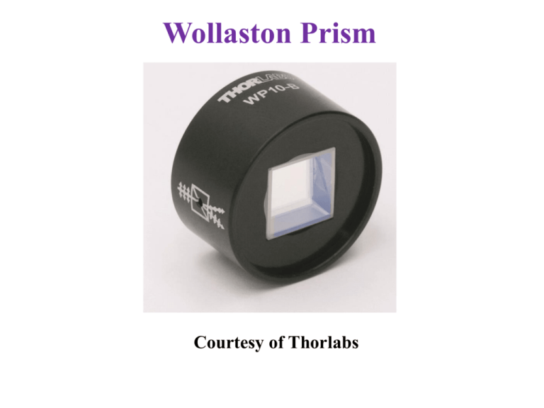
Wollaston Prism Courtesy of Thorlabs Optical Activity and Circular Birefringence An optically active material such as quartz rotates the plane of polarization of the incident wave: The optical field E rotated to E. If we reflect the wave back into the material, E rotates back to E. Optical Activity and Circular Birefringence Vertically polarized wave at the input can be thought of as two right and left handed circularly polarized waves that are symmetrical, i.e. at any instant a = b. If these travel at different velocities through a medium then at the output they are no longer symmetric with respect to y, a ≠ b, and the result is a vector E at an angle q to y. Optical Activity and Circular Birefringence q ( nL nR ) L Liquid Crystals Schematic illustration of orientational disorder in a liquid with rod-like mesogens. (a) No order, and rods are randomly oriented. (b) There is a tendency for the rods to align with the director, the vertical axis, in this example. Liquid crystal displays use polarized light and a liquid crystal to orient the polarization of the light passing through Photo by SK Liquid crystal displays emit polarized light There are 5 polarizers placed at different angles on the screen Photo by SK Liquid Crystal Displays Transmission based LCD. (a) In the absence of a field, the liquid crystal has the twisted nematic phase and the light passing through it has its polarization rotated by 90. The light is transmitted through both polarizers. The viewer sees a bright image. (b) When a voltage, and hence a field Ea, is applied, the molecules in the liquid crystal align with the field Ea and are unable to rotate the polarization of the light passing through it; light therefore cannot pass through the exit polarizer. The light is extinguished, and the viewer see dark image. Liquid Crystal Displays Plots of the rotation angle F of the linearly polarized light vs. the rms voltage Vrms across an LCD cell, and the normalized transmittance T(Vrms)/Tmax (%) vs. Vrms for a typical twisted nematic liquid crystal cell. Electro-Optic Effects Field induced refractive index New refractive index n = n + a1E + a2E2 + ... Linear electro-optic effect The Pockels effect Dn = a1E Second order electrooptic effect The Kerr effect Dn = a2E2 = (K)E2 Electro-Optic Effects Field induced refractive index n = n + a1E + a2E2 + ... Linear electro-optic effect. The Pockels effect Dn = a1E Friedrich Carl Alwin Pockels (1865 - 1913) son of Captain Theodore Pockels and Alwine Becker, was born in Vincenza (Italy). He obtained his doctorate from Göttingen University in 1888. From 1900 until 1913, he was a professor of theoretical physics in the Faculty of Sciences and Mathematics at the University of Heidelberg where he carried out extensive studies on electro-optic properties of crystals the Pockels effect is basis of many practical electro-optic modulators (Courtesy of the Department of Physics and Astronomy, University of Heidelberg, Germany.) Electro-Optic Effects Field induced refractive index n = n + a1E + a2E2 + ... Linear electro-optic effect. The Pockels effect Dn = a1E Various KD*P-based Pockels cells used for Q-switching in laser applications. Left, half-wave voltage V/2 of 6.8 kV nm, right, small, V/2 = 6.5 kV, right large, V/2 = 6.8 kV. The cells have AR (antireflection coatings), and can be used from UV to 1.1 mm. Note: KD*P is a KD2PO4 crystal. (Courtesy of Eksma Optics, Vilnius, Lithuania) Pockels Effect (a) A centrosymmetric unit cell (such as NaCl) has a center of symmetry at O. When the position vector r, from O to A, is reversed to become r, it points to B, which is identical to A. (b) An example of noncentrosymmetric unit cell. In this example, the hexagonal unit cell has no center of symmetry. When we reverse the position vector O A to become OB, B is different than A. Glasses and liquids exhibit no Pockels effect Dn = a1E a1 = 0 for all noncrystalline materials e.g. glasses and liquids Note: There may be exceptions if asymmetry is induced in the glass structure that destroys the structural isotropy Pockels Effect and the Indicatrix a) Cross section of the optical indicatrix with no applied field, n1 = n2 = no. (b) The applied external field modifies the optical indicatrix. In a KDP crystal, it rotates the principal axes by 45° to x and y and n1 and n2 change to n1 and n2. (c) Applied field along y in LiNbO2 modifies the indicatrix and changes n1 and n2 change to n1 and n2 . Pockels Effect n1 and n2 change to n1 and n2 n1 n1 n r Ea 1 2 3 1 22 Pockels coefficient 1 3 n2 n2 2 n2 r22 Ea Applied field Pockels coefficient r depends on the material and the crystal structure r = rij is a tensor quantity Transverse Pockels Cell Tranverse Pockels cell phase modulator. A linearly polarized input light into an electro-optic crystal emerges as a circularly polarized light. V = V/2 = Half-wave voltage, corresponds to Df = and generates a half-wave plate Transverse Pockels Cell Electro-optic phase modulator using LiNbO3. The socket is the RF modulation. (Courtesy of Thorlabs) Tranverse Pockels Cell Intensity Modulator (a) A tranverse Pockels cell intensity modulator. The polarizer P and analyzer A have their transmission axis at right angles and P polarizes at an angle 45° to y-axis. (b) Transmission intensity vs. applied voltage characteristics. If a quarter-wave plate (QWP) is inserted after P, the characteristic is shifted to the dashed curve. Tranverse Pockels Cell Intensity Modulator Eo Eo E xˆ cos(t ) yˆ cos(t Df ) 2 2 Pockels effect modifies this E Eo sin( 12 Df ) sin( t 12 Df ) Df f1 f2 I I o sin ( Df ) 2 1 2 V I I o sin ( ) 2 V / 2 2 2 no3 r22 L V d Tranverse Pockels Cell Intensity Modulator V I I o sin ( ) 2 V / 2 2 An applied voltage of V/2 is needed to allow full transmission. Example: Pockels Cell Modulator What should be the aspect ratio d/L for the transverse lithium niobate (LiNbO3) phase modulator that will operate at a free-space wavelength of 1.3 mm and will provide a phase shift Df of (half wavelength) between the two field components propagating through the crystal for an applied voltage of 12 V? At = 1.3 mm, LiNbO3 has no 2.21, r22 5×10-12 m/V. Example: Pockels Cell Modulator What should be the aspect ratio d/L for the transverse lithium niobate (LiNbO3) phase modulator that will operate at a free-space wavelength of 1.3 mm and will provide a phase shift Df of (half wavelength) between the two field components propagating through the crystal for an applied voltage of 12 V? At = 1.3 mm, LiNbO3 has no 2.21, r22 5×10-12 m/V. Solution Use Df = for the phase difference between the field components Ex and Ey, Df d 1 2 3 no r22V / 2 L Df 2 L V / 2 d 1 2 3 12 ( 2 . 21 ) ( 5 10 )(12) 6 (1.3 10 ) no3 r22 d/L 1×10³ This particular transverse phase modulator has the field applied along the y-direction and light traveling along the zdirection (optic axis). If we were to use the transverse arrangement in which the field is applied along the z-axis, and the light travels along the y-axis, the relevant Pockels coefficients would be greater, and the corresponding aspect ratio d/L would be ~10-2. We cannot arbitrarily set d/L to any ratio we like for the simple reason that when d becomes too small, the light will suffer diffraction effects that will prevent it from passing through the device. d/L ratios 10-3 10-2 in practice can be implemented by fabricating an integrated optical device.

