1 Type: Three phases, three windings oil immersed and installation
Date of / 3/2012.
TECHNICAL SPECIFICATIONS
TRANSFORMER 63MVA-110/22/6,3KV OF THE SUBSTATION
A. GENERAL
I. Ambient conditions
+ Altitude of Installation less than 1000m above sea level.
+ Ambient temperature: maximum: 45 0 C
average during 24 hour : 35 0 C
minimum: 0 0 C.
+ Climate condition: tropical.
+ Ambient humidity: average during 24h hour: 85%
maximum : 100%
+ Maximum speed of wind : 160km/h
+ earthquake factor: 0,1g
+ Degree of pollution level: Heavy.
+ Number days of storm per year : 40 days/ year.
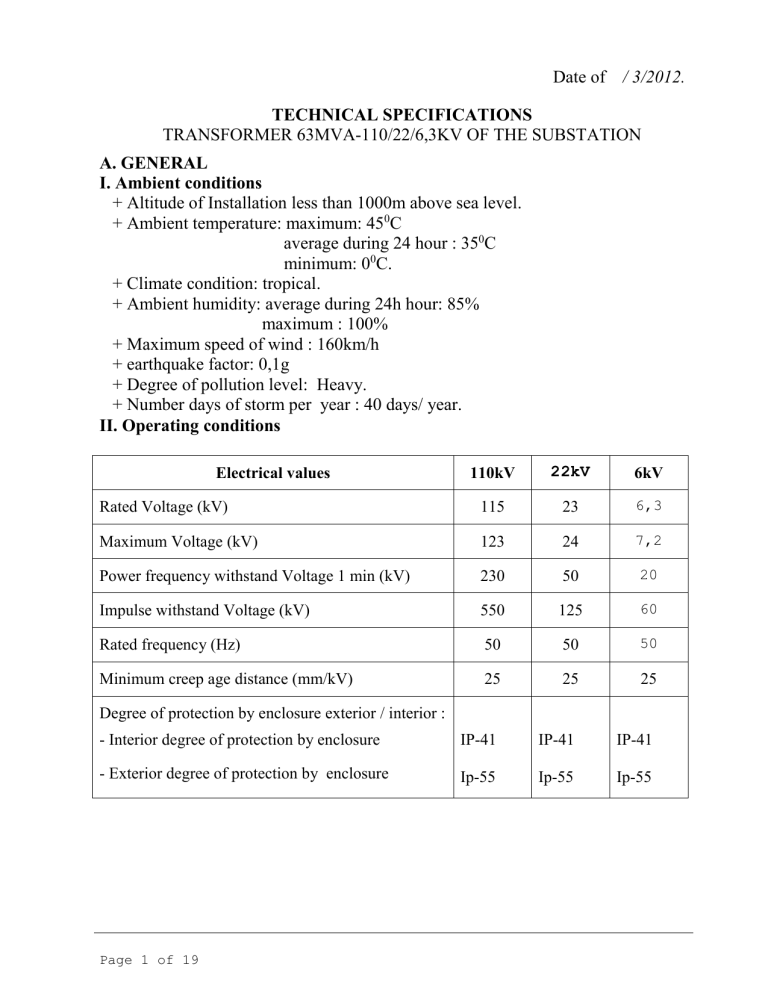
II. Operating conditions
Electrical values 110kV
22kV
6kV
Rated Voltage (kV) 115 23
6,3
Maximum Voltage (kV) 123 24
7,2
Power frequency withstand Voltage 1 min (kV) 230 50
20
Impulse withstand Voltage (kV) 550 125
60
Rated frequency (Hz) 50 50
50
Minimum creep age distance (mm/kV) 25 25 25
Degree of protection by enclosure exterior / interior :
- Interior degree of protection by enclosure
- Exterior degree of protection by enclosure
IP-41
Ip-55
IP-41
Ip-55
IP-41
Ip-55
Page 1 of 19
B. TECHNICAL CHARACTERISTICS
I. Standards
The design, manufacturing, materials, testing of the transformers shall comply with
General Technical Specifications, Special Technical Specifications and with the latest revision of the following IEC publications and Climate condition tropical:
IEC 60076 Power Transformers;
IEC 60137 Bushings for alternating voltages above 1 kV;
IEC 60185 (60044) Current Transformers
IEC 60296 Specification of unused mineral insulating oils for transformers and switchgear;
IEC 60529 Degree of protection by enclosure exterior/interior ( signals IP)
IEC 60354 Loading guide for oil-immersed transformers and reactors;
IEC 60551 Noise of Transformers and reactors.
IEC 60947 Supervision and cutting devices of low voltages.
IEC 60214, IEC 60352: On load tap changer devices.
II. Equipment main data.
63MVA – 110/22/6,3kV Transformer
1 Type: Three phases, three windings oil immersed and installation outdoor
Transformer.
2 Rated frequency: 50Hz
3. Rated Voltage:
HV: 115
9 x 1,78% kV (On load Tap changer).
MV: 23kV.
LV: 6,3kV (used for balanced winding)
4. Rated power on cooling system shall be natural oil- air forced (ONAF)
- HV winding : 63.000 kVA
- MV winding : 63.000 kVA
- LV winding : 21.000 kVA
5. Rated power on cooling system shall be natural oil –air (ONAN)
- HV winding: 50.400 kVA
- MV winding : 50.400 kVA
- LV winding : 16.800 kVA
6. Vector group and symbol:
- HV winding: neutral star connected.
- MV winding: neutral star connected .
- LV winding : open delta connected.
- Vector group and symbol: YNynd-12-11
7. Method of neutral system :
- HV: Directly Neutral earth.
- MV: Directly earth
- LV : Directly earth.
Page 2 of 19
8. Insulation level:
8.1 HV winding 115kV:
+ Maximum voltage ( r.m.s ): 123kV
+ Power frequency withstand 1min (r.m.s): 230kV
+ Impulse voltage (peak withstand level max): 550kV.
8.2 Neutral of HV winding
+ Maximum voltage( r.m.s ): 72,5kV
+ Power frequency withstands 1min (r.m.s): 140kV.
8.3 MV winding 23kV:
+ Maximum voltage( r.m.s ): 24kV
+ Power frequency withstand 1 min (r.m.s): 50kV
+ Impulse voltage (peak withstand level max): 125kV.
8.4 Neutral of MV winding:
+ Maximum voltage( r.m.s ): 20kV
+ Power frequency withstands 1min (r.m.s): 50kV.
8.5 LV winding 6.3kV
+ Maximum voltage( r.m.s ): 7,2kV
+ Power frequency withstand 1 min (r.m.s): 20kV
+ Impulse voltage (peak withstand level max): 60kV.
9. Method cooling: ONAN/ONAF.
10. Current fault shot time withstand ( peak short circuit withstand level)
+ HV : 40kA/3s
+ MV and LV: 25kA/3s
11. Minimum creep age distance (mm/kV): 25mm/kV.
12. Overload withstand: IEC-60354 standards.
13. Degree of temperature rise:
+ Temperature rise of top oil : 55 0 C
+ Temperature rise of winding : 60 0 C
14. Noise level: not exceed 80dB ( according to IEC-60551).
15. No-load loss: Po
39kW
16. No-load current: Io
0,19%.
17. On- load loss P k HV- LV
in 63MVA, 75 0 C, cos
= 1: P k
230kW.
18. Impedance voltage:
- U
HV- MV
% : 11%.
III. General requirements for transformer
1.Transformer Tank.
Transformer tank shall be constructed from high tensile strength steel plate. It shall be design to steady and withstand full vacuum. It shall furthermore be leakage free for hot transformer oil with an overpressure in tank of 10N/cm2 on three hour and without distortion or buckling, withstand vacuum 760mm Hg
Page 3 of 19
In side tank shall arrangement magnetic diaphragm. On the fitting current bushing position must be tackle re-induction current.
The transformer can move under all conditions.
The transformers can be vacuum pump on the fitted position. (including accessories)
The tank shall be provided with bolted type manholes for easy inspection and maintenance bushing and windings.
The tank shall be provided with iron ladder for inspection and maintenance.
In interior surface of tank and tube associated equipment shall be recover by permit oil material. On exterior surface of tank shall be recovered by permit oil and rain water material. Colors of tank must be suitable for radiation heat of transformer.
The transformer washers and gaskets shall permitted hot oil and min age above 15 year.
The tank shall be provided complete with:
+ valves on the pipes:
+ upper and lower filter valves.
+ Sampling devices at top and bottom of tank.
+ Draining valves and drain plug.
+ Vacuum pump valves.
+ Bicuspid valves for radiators.
2.Core and windings
The core shall be built up of high-grade, non-ageing, low-loss, high permeability, cold-rolled, grain-orientated silicon sheet steel.
The steel shall be of thin laminations, annealed after cutting and rolled, to ensure smooth surfaces at the edges. Both sides of each sheet shall be insulated with durable hot oil and heat-resistant baker enamel, varnish, or other chemical treatment, subject to the approval of the Employer's Representative.
The cores shall be clamped and braced to withstand, without damage or deformation, the forces caused by short-circuit stresses, transportation, or handling, and to prevent the shifting of the core laminations. The clamp assemble and structure shall be of a, non-magnetic type, and shall be effectively insulated and tightened so to ensure an even pressure on the whole core assembly and are not loosened by vibrations caused by transport and operation.
The core clamping structure shall not form closed loops and shall withstand a voltage, to the core and tank, of not less than 2.5 kV A.C per 1 min. It shall be earthed in one point, which shall be brought out through the cover and earthed externally.
The core shall be arranged suitable ducts for efficient oil cooling. Lifting eyes or lugs shall be provided at suitable points of the core assembly.
Page 4 of 19
The Winding shall be of electrolytic high quality copper, section and resistance must be equal. The windings must be construction steady and withstands forces caused by short-circuit stresses
- The insulation material shall be highly quality and designed as to obtain an optimal value for series and shunt capacities in order to have a favorable distribution of the voltage for full waves and chopped waves.
3.Bushings
- 115kV Bushings: type 123kV-800A, according to IEC-60137.
- Neutral 115KV Bushings : type 72kV-800A, according to IEC-60137.
The bushings shall be designed with test tap and prism a type glass with gasket.
- 23kV (phase and neutral): type glass 24kV-2000A
- 6,3kV: type glass 10,5kV-2000A.
4. Oil and gaskets system
4.1 Oil used for transformer and OLTC
Sufficient oil shall be supplied for the first filling of the transformers and all associated oil-filled equipment. The oil shall be a highly refined mineral oil suitable for use as an insulating and cooling medium in transformers. The oil shall be oxide- resistance but have not PCB and according to IEC 60296
4.2 Conservator of tank and OLTC
- The conservator shall be made to enable expansion of oil. For each conservator a synthetic diaphragm ensuring an airtight seal shall be provided.
- Conservator of main tank and conservator of OLTC shall be made separated.
- The conservator shall be connected to the main tank through a straight sloped pipe of Buchholz relay type.
- Inspection windows shall be provided for checking the diaphragm surface. Additionally, for protection of the space above the diaphragm, a silicagel air drier shall be provided. It shall be arrangement balance pressure valves.
- The conservator shall be fitted with valves:
+ Isolating valves shall permit the removal of Buchholz relay and flow oil relay
+ Oil filling plug, drain valve, oil test screw , lifting lugs, etc;
+ Safety vent;
- The thermometers of top oil and windings must arrangement advantage on the tank for somebody.
5 Cooling system
5.1. Fans
The fans system including two groups
Fans control : Manuel and auto operation.
The fans groups shall design separate operation and independence to make sure two fans not stop at on.
Page 5 of 19
Power supply for fans-motor: three phase 220/380V-50Hz.
The fans - motor high speed, low of noise and sign rotation.
The fans shall be safe kipping and separate protection by over temperature and magnetic equipments.
Fans control : local or remote in the control room.
The fans auto operation starts by top oil temperature and load carrying. A signal for start from phase B current bushing)
The radiators shall be provided with sectionalizing valves, to make possible their removal without disturbing the transformer.
Motor control by signal of top oil thermometer:
Stop fans : 45 0 C
Start fans : 55 0 C
Signal indicator: 85 0 C (for protection system)
The fans motor protections by MCB. The MCB operates over temperatures and magnetic.
The control and protection equipment of the fan- motors will be contained in a metallic weather-proof cabinet, mounted on the transformer and with provided :
- Turn switch auto or manual.
- Turn on and turn off
- Alarm indicator:
+ Fans ON
+ Fans OFF
+ Fans local
+ fans Auto
+ Faull
+ Supply Normal
5.2. Radiator
- The radiator shall be design and arrangement to enable easy cleaning and recover by hand.
- The bicuspid valves flow sign and can close and open position.
- The radiator provided with: upper lugs, under lugs, lifting and drain oil, and drain air.
6 Regulation Voltage.
6.1. On load tap changers:
- Manufacture:
- Power supply for motor operating: three phases 220V/380V - 50HZ
- Power supply for control and signal circuit : 220V-DC and single phase 220V-AC-1 phase-50Hz
Page 6 of 19
- OLTC control:
+ Manuel by crank.
+ Auto: Local and remote.
+ Remote control can by manual or auto regulator voltage equipment.
- OLTC shall be protection: overload, fault motor, and circuit control, under voltage and unbalanced voltage, revert voltage protection.
- The control cabinet shall contain:
+ MCB and contactors for the different circuits;
+ Motor protection relays and ampere meters for the fans;
+ Time registration of service hours of fans;
+ A three-position reversing switch for each fan circuit with on, off and automatic.
+ Lighting;
+ Necessary terminal blocks;
+ Thermostat controlled heating element for anti-condensation purposes;
6.2 On Load Tap changer equipment
Supervision and regulation voltage equipment (On load auto regulation voltage equipment) auto control OLTC.
On load auto regulation voltage provided any characteristic of load.
On load auto regulation voltage shall be supervision, lock out, signal and parallel
Transformers functions.
Auto regulation voltage assembled in remote control cubicle.
Equipment main data:
- Auto regulation voltage digital relay used three phases Transformer.
- Permissible variation voltage: 85-140V
- Power supply: 85-115V AC
- Rated frequency : 50Hz
- Rated current : 1A
- Auto operation when
U=0,5-5%, step 0,1%.
- Peak up time: 0-180s, invert and independent characteristics.
- Time between two steps: 0-10s
- Lock out low voltage: 70-95%Us, step 1%.
- Detect high voltage: 105-130%Us, step 1%.
- Lock out over current: 100-150% I n
and 5-50% I b
, step 5%
( I n
: rated current; I b
: balance current in parallel Transformers operating)
- Supervision parallel two or more transformers operating.
- Equipment shall be provided compensate function : ∆U of line
- Equipment shall be provided compensate resistance of load.
- Equipment shall be provided load shedding of function.
Page 7 of 19
- Equipment shall be provided supervision tap changers in times of step by step. If over time set, equipment start lock out and alarm or start protection.
- Changer manual and auto function.
- LCD normal alarm on the interface of voltage value operating from current transformer to relay.
- Can be connection and SCADA system via usual interface (RS-232/485).
7 Bushings current transformer.
7.1. HV bushing current transformers
- Must be three secondary winding.
- Ratio primary / secondary : 200-400-600/1/1/1A.
- Accuracy class and burden:
+ 01 winding for measure: CL 0,5-30VA
+ 02 winding for relay protection : CL5P20-30VA.
Current transformer used supervision HV winding temperature arrangement on B phase bushing. It shall be one secondary winding, accuracy class 1 and burden 10VA, ratio primary/secondary : 300/1,5A.
7.1.2 Current transformer used auto voltage regulation (AVR) arrangement on A phase bushing. It shall be one secondary winding, accuracy class 1, and burden
10VA, ratio primary/secondary: 300/1A
7.2 HV Neutral bushing current transformer
HV Neutral bushing current transformer must be 01 secondary winding, ratio primary/secondary 200-400-600/1/1A, accuracy class 5P20, and burdens: 30VA accuracy class 1 used to protection and accuracy class 2 used to reserve protection.
7.3 MV 23kV current transformer bushings
- 03 current transformers fitted in 22kV bushings use 01 CT accuracy class 2:
- Accuracy Class: 5P20
- burden: 30VA.
- ratio Primary/secondary : 800-1200-2000/1/1A.
-Current transformer used supervision MV 23kV winding temperature arrangements on B phase bushing. It shall be one secondary winding, accuracy class 1, and burden
10VA, ratio primary/secondary : 1500/1,5A.
7.4 MV Neutral bushing current transformer
HV Neutral bushing current transformer must be 01 secondary winding, ratio primary/secondary 1200-1600/1A, accuracy class 5P20, and burdens: 30VA used to earthing protection.
8. Local cabinet control and remote control cubicle
8.1. Local control cabinet
Page 8 of 19
Each transformer shall be fitted with a control cabinet of welded sheet steel housing, mounted on the transformer tank with vibration dampers, in a position easily accessible from ground level.
- The cabinet made by steel plate thick over 3mm. The cabinet fitted on the transformer tank. Degree of protection by enclosure : IP41
The cabinet shall contain all control and protective equipment for the cooling fan system, as well as the termination of all secondary circuits.
The internal arrangement of the cabinet shall keep the various circuits clearly separated from each other, permitting easy and safe independent maintenance and repair of each of them without disturbing the others.
The control cabinet shall contain:
- MCB and contactors for the different circuits;
- Motor protection relays and ampere meters for the fans;
- Time registration of service hours of fans;
- A three-position reversing switch for each fan circuit with on, off and automatic.
- Lighting;
- Necessary terminal blocks;
- Thermostat controlled heating element for anti-condensation purposes;
+ Control switch local-remote
+ Control switch manual- auto)
+ Alarm indicator cooling system:
Fans ON
Fans OFF
Fans on manual operation
Fans on auto operation
Faull fans
Supply normal
8.2. Remote control cubicle (AVR):
- The cubicle made by steel plate thick over 3mm. The cubicle fitted on control room.
Degree of protection by enclosure : IP41.
- The cubicle arrangement equipment on front of, the on rear arrangement a back door..
- Lighting turn on when the door open; thermo starter start by sensor temperature.
- The cubicle shall be recovered by RAL-1019 color.
The remote control cubicle shall contain:
+ Remote turn switch ON, OFF cooling system
+ switch control Local-remote
+ Switch control manual- auto
+ Alarm indicator cooling system:
Page 9 of 19
Fans ON
Fans OFF
Fans on manual operation
Fans on auto operation
Faull fans
Supply normal
Equipment for remote control voltage:
+ Remote control OLTC
+ Switchgear manual- auto
+ Remote turn switch RISE upper, DOWN lower
+ Emergency stop
+ Parallel switch .
+ Matter switch and slave switch.
+ Indicator position LCD.
+ Alarm indicator OLTC system:
OLTC operating
OLTC on uppermost position
OLTC on lowermost position
Switchgear on Remote or Local
Faull motor operation
Fault on changer switchgear
supply normal
+ Alarm level oil, temperature oil and temperature winding.
+ Auto regulation voltage relay (F90).
Over voltage, under voltage protection. Over current lock out auto regulation voltage
+ Alarm and indicator for transformer protection.
+ Test switch.
+ Intermediary relay, fuse, connector, automat, terminal blocks, trademark...
9. Cable connecting
Cable connected equipment on the transformer shall be provided:
- Rated voltage: 0,6/1kV, according to IEC-3/C.
- Technical characteristic:
+ Core copper spin according to IEC-60228
+ Compound insulation, discriminate core by number sign on.
+ Dunn age by compound material.
+ grid copper
+ Addition corrosion material .
+ Over coat by compound black material.
Page 10 of 19
10. Earth Connection.
All sections is not carrying electrical, cubicle, frame of equipment must be designed earth terminals.
11. Supervisions and protection equipment
Transformer shall be provided including:
Buchholz relay with two alarm and one tripping contact and gas test pipe.
Magnetic oil level gauge of tank calibrated in 0 C with maximum and minimum level shall be signaled by appropriate alarm 02 contacts.
Magnetic oil level gauge of OLTC calibrated in 0 C with maximum and minimum level shall be signaled by appropriate alarm 02 contacts.
The top oil thermometer type oil thermometers with needle and scale 0-160 0 C. It shall be with max needles and with compensation functions.
The thermometer with 4 bands temperature and 4 double contacts ( normal open)
The thermometer can be connect display screen remote.
Three themometers for temperature indicator 115KV and 23KV and 10,5kV windings. Thermometers with needle and scale 0-160 0 C, It shall be with max needle and with compensation functions.
The thermometer with 4 bands temperature and 4 double contacts ( normal open)
The thermometer can be connect display screen remote
Flow oil relay with 01 contact signal trip circuit break.
Pressure valves with 01 contact signal trip circuit breaker ( Operating when pressure oil in tank unexpected rise).
- Pressure relay with 01 contact signal trip circuit breaker .
Rapid pressured envelope ( drain oil when pressure of oil unexpected in tank).
After filling oil must fill nitrogen make decrease. Oil separate air by rubber envelope on conservator.
12. Terminals and clamps
- 115kV direction : Terminal and clamp out side used ACSR 240-300mm 2 connector.
- Neutral 115kV: Terminal and clamp out side used M 240-300mm 2 conductors and insulator frame.
- 23kV direction: Terminal and clamp out side used two wire cables of XLPE/PVC-
24kV 400mm 2 /phase.
- 6,3kV direction: Outdoor Terminal and clamp out side used solid copper
(connected 02 open delta terminal and earthing)
13. Trademark and equipment on Tank
The trademark made by steel plate thick over 2mm and not oxide. It shall be permitted rain water and fitted in a position easily for operating
Information content:
Page 11 of 19
+ Symbol, Type, Year and standards manufacture.
+ Number.
+ Rated power capacity of winding ( on ONAN/ONAF).
+ Insulation level.
+ Degree temperature rise of oil, windings.
+ Rated voltage and step by step level voltage regulation .
+ Rated current of windings.
+ Vector group symbol .
+ Impedance voltage.
+ No-load current.
+ Weight: Total, transport, core and winding and weight oil.
+ Dimension: Total and transport.
+ Diagram of windings connected and current transformer bushing connected.
+ Ratio voltage and voltage on position of tap changer.
+ Ratio and burden, accuracy class of current transformer bushings.
+ Guide of operation.
All equipment accessories shall be sign and guide on operating and maintenance.
14. Weight of Transformer
According to manufacture.
15. Dimensions of Transformer
Total dimension of transformer (including radiator...).
IV Factory Tests and complete transformers
The following tests shall be carried out at the Manufacturer's works in the presence of the Employer's Representative on transformers to be provided, in accordance with the requirements set out in IEC Publication No. 60076-1 and test results shall be furnished to the Employer's Representative after conclusion of the tests for consideration.
1 Measurement of winding resistance.
2 Material Insulation tests
+ Measurement R60/R15 insulation of windings and tank.
+ Measurement tg
of windings and tank.
+ Measurement capacitance of winding and tank.
3 Measurement of voltage ratio and vector group.
4 Measurement of no-load losses and current tests at rated voltage and frequency;
5 Measurement of load-losses at rated voltage and frequency;
Page 12 of 19
6 Measurement of impedance voltage, short circuit impedance, and zero-sequence impedance at rated current and frequency on medium and extreme taps;
7 Inductance over voltage at 100Hz or 200Hz withstand test;
8 Power frequency voltage withstand test;
9 Oil test and function tests on auxiliary equipment.
10 Power cable tests.
11 Measurement of noise level and the power absorbed by cooling system.
12 Auxiliary equipment tests including:: bushings, oil temperature gauge, winding temperature gauge, safety valves, oil flow relay, pressure relay ... magnetic oil level gauge, current transformer bushings.
Tests report shall be including : full function test, diagrams test, result tests and equipment used in testing.
Equipment used in testing must be certification quality by quality national.
Supplier shall be sending to plan of factory tests before 20days. The plant shall be conform and supervision in during testing.
V. Spare Equipments.
- 01 bushing terminal 115kV
- 01 bushing terminal 23kV
- 01 bushing terminal 6,3kV
- 01 fan and 01 contactor.
- silica gel...., use on full time maintenance .
VI. Assembly, testing and check before acceptance.
The Power transformers are located, tests, sign on conform closed electrical and check and take over by professional of manufacture. Check and take over group control and to witness 72 hour on construction site.
To assign transfer and test reports on construction sit according to fix standards.
VII. Technical Documents
1 Arrangement document
Within 60 days of receipt of sign contract , Manufacture supplies 03 documents templates and drawings:
Dimensions drawing of transformer.
Drawing guide for design foundation of Transformer
Documents of Transformer and accessories.
Drawing cooling system and changers voltage control.
Drawing connected of internal transformer.
Drawing fitted cabinet.
Page 13 of 19
If content of document difference of contract, manufacture must to report and notice boar to compare of difference parts.
After received letter , within 05 days, buyer will be make answer by letter.
After received request, manufacture supplies document corrected until approval by buyer.
2.Technical Documents
Before transfer equipment 10 days, manufacture supplies 08 document templates:
+ Technical document of transformer and accessories.
+ Drawings of principle, connected and arrangements accessories.
+ Documents of guide use to fitting, operating and maintenance Transformer.
+ Documents of guide use to fitting, operating and maintenance accessories of
Transformer from manufacture equipments.
+ Tests reports Transformer and accessories.
If results of tests report not to meet demean in technical characteristic board on document to make an offer, the treatment will treat according to contract.
VIII Technical specifications and undertakes transformer 115/23/6,3kV-63MVA
TT
1 Manufacture
2 Type
Technical
2.1 Shell or Core
2.2 Auto or separated
2.3 Three or single phase
2.4 Method Cooling
2.5 Vector group symbol
3 Distributed Power
3.1 HV winding
3.2 MV Winding
3.3 LV Winding
4 Maximum Power on ONAF
4.1 HV winding
4.2 MV winding
4.3 LV winding
5 Maximum power on ONAN
5.1 HV winding
5.2 MV winding
5.3 LV winding
6 Impulse withstand level ( peak withstand level max)
6.1 HV winding
6.2 MV winding
6.3 LV winding
Unit
MVA
MVA
MVA
MVA
MVA
MVA
MVA
MVA
MVA kV kV kV requirement
3 phase, 3 coil, oil, ourdoor, type open
Core separated
Three phase
ONAN/ONAF
YNynd-12-11
63
63
21
63
63
21
50,4
50,4
16,8
550
125
60 undert akes
Page 14 of 19
7 Power frequency withstand voltage
7.1 HV winding
7.2 MV winding
7.3 LV winding
7.5 Minimum leakage current length
8 Temperature rise on rated power
8.1 Winding
8.2 Oil ( top oil)
9 Auto – induction maximum in core on
Rate voltage and rate frequency
9.1 In core magnetic
9.2 Out core magnetic
9.3 Stock of core
9.4 magnetic diaphragm
10 Density of current in wingding on rate power
10.1 HV winding
10.2 MV winding
10.3 LV winding
11 No Load loss
11.2 No load current
12.1 On- load loss P
HV- LV on 63MVA (in 75
C, cos
= 1)
0
13 Impedance voltage in 75
0
C Uk (HV-MV):
14 Direct dependence winding in 75 0 C
14.1 HV
14.2 MV
14.3 LV
15 Type and Method arrangement of winding
15.1 HV
15.2 MV
15.3 LV
15.4 Regulator Voltage
16 Material of winding
16.1 HV
16.2 MV
16.3 LV
16.4 Regulator voltage of winding
17 Insulation winding
17.1 HV
17.2 MV
17.3 LV
17.4 Regulator voltage of winding
18 Type core of transformer
18.1 Country kV kV kV mm/kV
0
C
0
C
T
T
T
T
%
/phase
/phase
/phase
A/mm 2
A/mm
2
A/mm
2
KW
%
KW
Page 15 of 19 confirm confirm confirm confirm confirm confirm confirm
39
0,19
230
230
50
20
25
60
55
11% confirm confirm confirm confirm confirm confirm confirm confirm confirm confirm confirm confirm confirm confirm confirm confirm
18.2 Type, manufacturer
18.3 Load loss of core in 1,5 Tesla
19 On load Tap changer devices (type, manufacture, method regulation)
19.1 Country
19.2 Type, manufacturer
19.3 Step by step level voltage regulation
19.4 Number steps
20 Bushing Insualator HV
20.1 Country
Phase insulator (A,B,C) confirm
Neutral Insulator
20.2 Type, Model, Manufacturer
Phase insulator (A,B,C)
Neutral Insulator
20.3 Rated Voltage and Current
Phase insulator (A,B,C)
Neutral Insulator
21 Medium voltage Bushing Insulator
(phase and neutral)
21.1 Country
21.2 Type, Model, Manufacturer
22.3 Rated Voltage and Current
22 Low voltage bushing insulator
22.1 Country
22.2 Type, Model, Manufacturer
22.3 Rated Voltage and Current
23 Bushing HV Current transformer
23.1 Country
23.2 Type, Model, Manufacturer
23.3 Rated Voltage
23.4 Ratio
Measurement, Protection
AVR
Coil temperature measurement
23.5 Accuracy
Measurement, Protection
AVR
Coil temperature measurement
23.6 Rated Capacity
Measurement, Protection
AVR
Coil temperature measurement
24 Neutral Bushing HV Current transformer
W/kg
% step confirm confirm confirm confirm
1,78 Un
19 confirm confirm kV, A kV; A kV; A kV m/n (A)
115kV; 800A
72kV; 800A confirm confirm
23kV; 2000A confirm confirm
10,5kV, 2000A confirm confirm
115
200-400-600/1/1/1A
300/1A
300/1,5
0.5, 5P20
1
1
30
10
10
Page 16 of 19
24.1 Country
24.2 Type, Model, Manufacturer
24.3 Rated Voltage
24.4 Ratio
Protection
24.5 Accuracy
Protection
24.6 Rated Capacity
Protection
25 Bushing MV Current transformer
25.1 Country
25.2 Type, Model, Manufacturer
25.3 Rated Voltage
25.4 Ratio
Measurement, Protection
Coil temperature measurement
25.5 Accuracy
Measurement, Protection
Coil temperature measurement
25.6 Rated Capacity
Measurement, Protection
Coil temperature measurement
27 Insulated Oil
27.1 Country
27.2 Type, Model, Manufacturer
27.3 Cable Supporting structure
28 Cooling Fan
28.1 Country
28.2 Type, Model, Manufacturer
29 Gas relay
29.1 Country
29.2 Type, Model, Manufacturer
30 Oil current relay
30.1 Country
30.2 Type, Model, Manufacturer
31 Pressure relay
31.1 Country
31.2 Type, Model, Manufacturer
32 Oil level meter
32.1 Country
32.2 Type, Model, Manufacturer
33 Oil level meter of OLTC kV m/n (A)
VA kV m/n (A)
VA confirm confirm
72
200-400-600/1/1A
5P20
30 confirm confirm
24
800-1200-2000/1/1A
1500/1,5A
0,5; 5P20
1
30
10 confirm confirm confirm confirm confirm confirm confirm confirm confirm confirm confirm confirm confirm
Page 17 of 19
33.1 Country
33.2 Type, Model, Manufacturer
34 Oil temperature meter
34.1 Country
34.2 Type, Model, Manufacturer
35 HV Coil measurement meter
35.1 Country
35.2 Type, Model, Manufacturer
36 MV Coil measurement meter
36.1 Country
36.2 Type, Model, Manufacturer
37 LV Coil measurement meter
37.1 Country
37.2 Type, Model, Manufacturer
38 Material manufactured etal of Power transformer
38.1 Country
38.2 Type, Model, Manufacturer
38.3 Thickness
39 Cover material metal of Power transformer
39.1 Country
38.2 Type, Model, Manufacturer
39.3 Thickness
40 Bottom material metal of Power transformer
40.1 Country
40.2 Type, Model, Manufacturer
40.3 Thickness
41 Radiator
41.1 Country
41.2 Type, Model, Manufacturer
41.3 Thickness
41.4 Sheds
42 Net weight of Oil
43 Minimum filling oil in Power transformer during transportation
44 Required oil for operation
45 Weigth of steel core and coil
46 Copper weight
47 Steel core weight mm mm mm mm
Liter
Liter
Liter
Ton
Ton
Ton
Page 18 of 19 confirm confirm confirm confirm confirm confirm confirm confirm confirm confirm confirm confirm confirm confirm confirm confirm confirm confirm confirm confirm confirm confirm confirm confirm confirm confirm confirm confirm confirm
48 Total weigth of power transformer
(without oil)
49 Weight for Transportation
50 Dimension for Transportaiton
50.1 Height
50.2 Width
50.3 Length
51 Noise leve ( 3 meters distance)
52 Dimension after installation
52.1 Height
52.2 Width
52.3 Length
53 30% Over voltage withstand duration
54 Technical and drawing
55 Type test, rountine test
Ton
Ton m m m dB m m m s confirm confirm confirm confirm confirm confirm
<=80 confirm confirm confirm confirm confirm confirm confirm
Page 19 of 19

