127-07_Magnetic_Force_2
advertisement
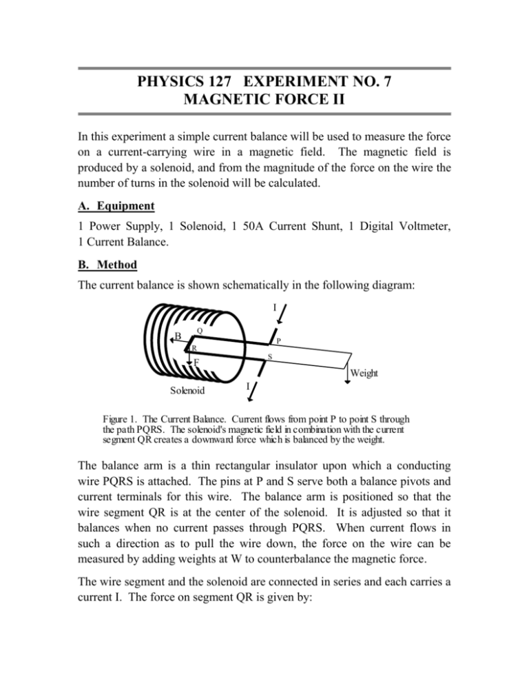
PHYSICS 127 EXPERIMENT NO. 7 MAGNETIC FORCE II In this experiment a simple current balance will be used to measure the force on a current-carrying wire in a magnetic field. The magnetic field is produced by a solenoid, and from the magnitude of the force on the wire the number of turns in the solenoid will be calculated. A. Equipment 1 Power Supply, 1 Solenoid, 1 50A Current Shunt, 1 Digital Voltmeter, 1 Current Balance. B. Method The current balance is shown schematically in the following diagram: I Q B P R S F Weight Solenoid I Figure 1. The Current Balance. Current flows from point P to point S through the path PQRS. The solenoid's magnetic field in combination with the current segment QR creates a downward force which is balanced by the weight. The balance arm is a thin rectangular insulator upon which a conducting wire PQRS is attached. The pins at P and S serve both a balance pivots and current terminals for this wire. The balance arm is positioned so that the wire segment QR is at the center of the solenoid. It is adjusted so that it balances when no current passes through PQRS. When current flows in such a direction as to pull the wire down, the force on the wire can be measured by adding weights at W to counterbalance the magnetic force. The wire segment and the solenoid are connected in series and each carries a current I. The force on segment QR is given by: F BI l (1) where l is the length of the segment QR and B is the magnetic field of the solenoid. In the long solenoid approximation, the magnetic field B is given by: NI L (2) where N is the total number of turns in the solenoid, and L is the length of the solenoid (see pp. 726-727 in the 7th ed. or pp. 819-820 in the 8th ed. of the text). The force on QR can then be written: B 0 F 0 Nl 2 I L (3) Q1. In what direction would F point if I were reversed: (a) In the current balance and not in the solenoid? (b) In both the current balance and the solenoid? C. Procedure Connect the solenoid and the wire PQRS in series in such a way that the force on RQ will be down. You should decide beforehand how this connection is to be made. Adjust the balance so that it is horizontal when no current flows through the wire. You will be supplied with several lengths of thin wire whose weight can be determined. Hang one of these wires at the notches on the outer end of the current balance. Turn up the solenoid/balance combination until balance is achieved. Record the weight of the wire and the corresponding balance current. Repeat the measurement several times to determine the uncertainty in the balance current. Repeat the above procedure with at least five other weights. Q2. Plot the magnetic force as a function of the square of the balance current. Be sure to show appropriate error bars for each point. Q3. From the slope of the plot in Q2, find the number of turns in the solenoid, Q4. In the derivation of equation (3), we did not consider the forces on wire segments PQ and RS. Was this justified? Explain. Q5. Does neglecting the forces on segments PQ and RS result in the value you got for the number of turns being larger or smaller than the actual value? Explain.
