Using your volt/ohm meter to analyze irrigation system electrical wiring
advertisement
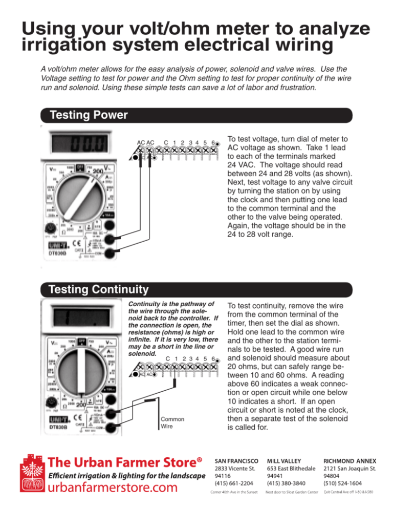
Using your volt/ohm meter to analyze irrigation system electrical wiring A volt/ohm meter allows for the easy analysis of power, solenoid and valve wires. Use the Voltage setting to test for power and the Ohm setting to test for proper continuity of the wire run and solenoid. Using these simple tests can save a lot of labor and frustration. Testing Power AC AC C 1 2 3 4 5 6 To test voltage, turn dial of meter to AC voltage as shown. Take 1 lead to each of the terminals marked 24 VAC. The voltage should read between 24 and 28 volts (as shown). Next, test voltage to any valve circuit by turning the station on by using the clock and then putting one lead to the common terminal and the other to the valve being operated. Again, the voltage should be in the 24 to 28 volt range. Testing Continuity Continuity is the pathway of the wire through the solenoid back to the controller. If the connection is open, the resistance (ohms) is high or infinite. If it is very low, there may be a short in the line or solenoid. C 1 2 3 4 5 6 Common Wire To test continuity, remove the wire from the common terminal of the timer, then set the dial as shown. Hold one lead to the common wire and the other to the station terminals to be tested. A good wire run and solenoid should measure about 20 ohms, but can safely range between 10 and 60 ohms. A reading above 60 indicates a weak connection or open circuit while one below 10 indicates a short. If an open circuit or short is noted at the clock, then a separate test of the solenoid is called for.

